| –
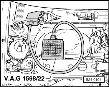
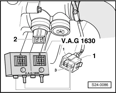
| Connect test box -V.A.G 1598/22 - at wiring loom to the 1AV control unit. |
| –
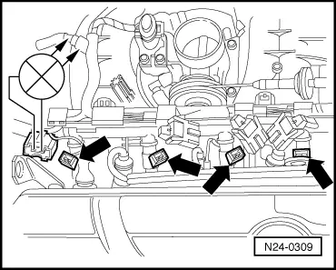
| Check wiring between the test box and the plugs from the injection valves for open circuit according to the current flow diagram. |
|
| Plug on cylinder 1, contact 2+bush 3 |
|
| Plug on cylinder 2, contact 2+bush 80 |
|
| Plug on cylinder 3, contact 2+bush 58 |
|
| Plug on cylinder 4, contact 2+bush 65 |
|
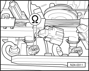
| Cable resistance: max. 1.5 Ω |
| –
| Also check the wires for short-circuits. |
| –
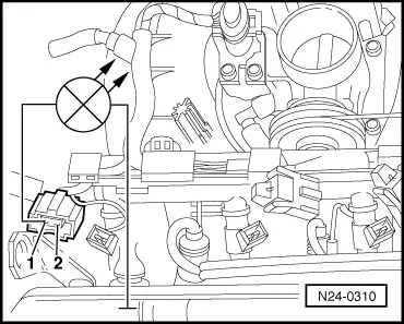
| Check wiring between the contacts 1 of the plugs for the injection valves for open circuit. |
|
| Cable resistance: max. 1.5 Ω |
| –
| Also check the wires for short-circuits. |
| Testing resistances of the injection valves |
|
|
|
 Note
Note