skoda Workshop Repair Guides

Skoda Workshop Service and Repair Manuals

Adapt the engine control unit to the electronic immobiliser > < Test intake air temperature sender
Testing voltage supply for engine control unit
Special tools and workshop equipment required
t  Vehicle system tester -V.A.G 1552 - with cable -V.A.G 1551/3-
t  Test box -V.A.G 1598/22-
t  Hand-held multimeter e.g. -V.A.G 1526 A - or multimeter -V.A.G 1715-
t  Measuring tool set -V.A.G 1594 A -
t  Current flow diagram
Test conditions
l  Battery voltage at least 11 volts
l  AC generator o.k.
   
l  Fuses no. 10 and 29 must be o.k.
Test sequence
–  Connect vehicle system tester -V.A.G 1552- and select engine electronics control unit with the address word 01. The engine must be idling for this step. (Connecting up the vehicle system tester and selecting the engine electronics control unit → Chapter).
  S97-0319
Read-out on display:
–  Enter 08 for the function “Read measured value block” and confirm the entry with Q.
 
Vehicle system test               HELP
Select function XX
Read-out on display:
–  Enter 002 and confirm with key Q.
 
Read measured value block     HELP
Enter display group number XXX
Read-out on display:
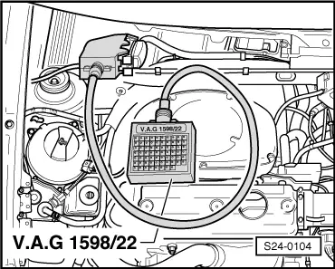
–  Read off read-out in display field 3.
   Specified value: approx. battery voltage
–  Press key.
–  Enter 06 for the function “End output” and confirm with key Q.
–  Switch off ignition.
If the specified value is not reached:
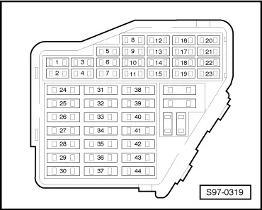
Testing voltage supply of the terminal 30
 
Reading measured value block 2     ->
    800/rpm      3.31 ms    14 V   25 °C
–  Connect test box -V.A.G 1598/22 - at wiring loom to the engine control unit.
–  Measure supply voltage with the multimeter and adapter cables from -V.A.G 1594 A- between the bushes 2+3 of the test box:
   Specified value: min. 11 V
Testing voltage supply of the terminal 15
–  Switch on ignition.
–  Measure supply voltage with the multimeter and adapter cables from -V.A.G 1594 A- between the bushes 2+1 of the test box:
   Specified value: min. 11 V
If the specified values are not reached:
–  Test cable connections to relay plate according to the current flow diagram.
  S24-0104

Adapt the engine control unit to the electronic immobiliser > < Test intake air temperature sender