skoda Workshop Repair Guides

Skoda Workshop Service and Repair Manuals

Inspecting semi-automatic tensioning pulley > < Removing and installing V-ribbed belt
Removing and installing, tightening the timing belt
  Note
Before removing the timing belt, mark direction of running. Reversing the rotation direction of an already used belt may destroy it.
1 - Bottom toothed belt guard
–  unscrew to remove the vibration dampener → Chapter
2 - Middle toothed belt guard
3 - 10 Nm
–  replace
4 - Engine support bracket
–  removing → Anchor
5 - 45 Nm
6 - Top toothed belt guard
7 - Timing belt
–  before removing mark running direction
–  check for wear
–  do not kink
–  removing → Anchor
–  installing → Anchor
8 - 25 Nm
9 - Washer
10 - 100 Nm
–  to release and tighten use the counterholder -MP 1-216-
11 - Camshaft sprocket
–  with sensor rotor for the Hall sensor -G40-
–  Removing and installing timing belt → Anchor
–  Installation position fixed by woodruff key -pos. 14-
12 - Toothed belt guard
13 - 10 Nm
14 - Woodruff key
–  check tightness
15 - Hall sender -G40-
–  when bolting on, ensure base plate is centered
16 - 10 Nm
17 - Rear timing belt guard
18 - 20 Nm
19 - Semi-automatic tensioning pulley
–  check semi-automatic tensioning pulley → Chapter
–  Fitting position → Fig.
20 - Coolant pump
–  removing and installing → Chapter
21 - 15 Nm
22 - Timing belt gear - crankshaft
–  there must not be any oil present on contact surface between timing belt sprocket and the crankshaft
–  can be installed only in one position
23 - 90 Nm + torque a further 1/4 turn (90°)
–  replace
–  counter-hold → Chapter with counter-holder -T30004- or counterholder -MP 1-310- for slackening and tightening
  S13-0103
Fitting position of the semi-automatic tensioning pulley
The angle bracket -arrow- must engage in the recess at the cylinder head.
Special tools and workshop equipment required
t  Torque wrench
t  Counterholder -MP 1-216-
t  Two-hole nut turner -T10020-
t  Counterholder -MP 1-310-
t  Supporting device - MP 9-200-
Removing toothed belt
Engine installed
–  Remove V-ribbed belt → Chapter.
–  Remove ribbed V-belt tensioning device.
  A13-0078
–  Rotate crankshaft to TDC of cylinder 1 -arrow- (vehicles with manual gearbox).
TDC marking on flywheel and reference mark must be aligned.
  A13-0081
–  Rotate crankshaft to TDC cylinder 1 -arrow- (vehicles with automatic gearbox).
TDC marking on drive plate and reference mark must be aligned.
  Note
  A13-0043
When engine removed, position vibration damper to TDC cylinder 1 -arrows-.
–  Remove engine cover.
  A13-0076
–  Insert supporting device -MP 9-200- and take up weight of engine with the spindle of the supporting device (only on right).
–  Remove vibration damper.
–  Remove top, bottom and middle timing belt guard.
–  Unscrew the reservoir for the power-assisted steering.
  S13-0104
–  Unbolt engine support from engine console and engine console from body -arrows-.
–  Mark the rotation direction of the timing belt.
–  Slacken semi-automatic tensioning pulley and take off toothed belt.
–  Turn crankshaft slightly back.
  A13-0063
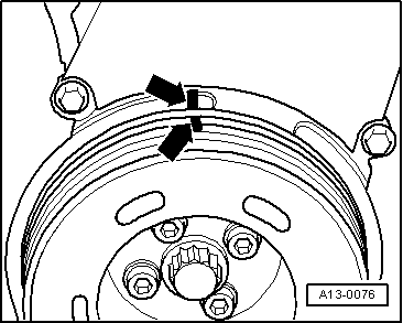
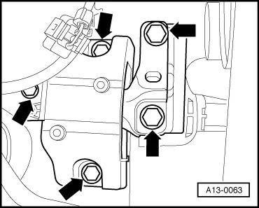
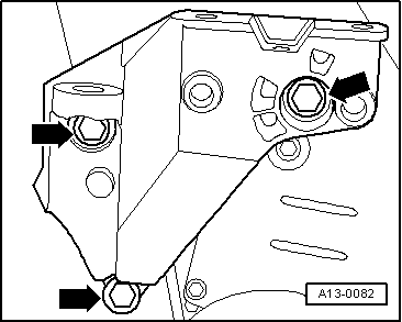
–  Unbolt engine support from engine -arrows-.
  Note
t  
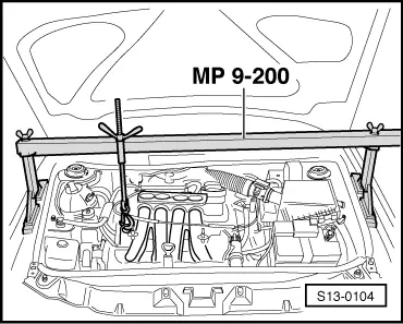
To slacken the front bolt of the engine support, raise engine slightly with spindle of supporting device -MP 9-200-.
t  To take off engine support, raise or lower engine, respectively with the supporting device -MP 9-200-.
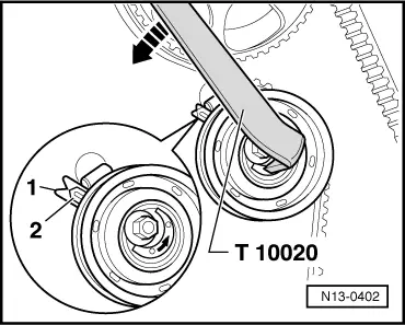
Installing toothed belt, tensioning (setting timing)
  Note
t  Also when carrying out repairs which necessitate taking the toothed belt only off the camshaft sprocket, it is then necessary to carry out the installation of the toothed belt as follows.
t  
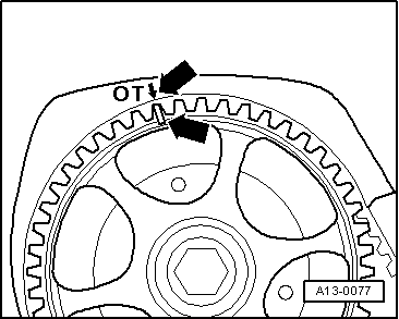
When rotating the camshaft, the crankshaft must not be positioned at TDC. Risk of damaging valves and piston crowns.
Precondition
l  The pistons must not be positioned at top dead centre.
  A13-0082
–  Bring the marking on the camshaft sprocket in line with the marking on the rear timing belt guard -arrows-.
–  Position crankshaft to TDC cylinder 1 (except when engine removed) → Anchor.
–  Fit timing belt onto the crankshaft timing belt sprocket (pay attention to direction of running) → Chapter.
  Note
  A13-0077
When engine removed, install bottom toothed belt guard and vibration damper. Position crankshaft to TDC of cylinder 1 arrows.
–  Fit timing belt onto tensioning pulley and onto camshaft sprocket.
  A13-0076
–  Pay attention to installation position of semi-automatic tensioning pulley:
t  The angle bracket -arrow- must engage in the recess at the cylinder head.
  A13-0078
–  Tighten the timing belt. Turn with -T10020- at centering piece to the left (in direction of arrow) up to the stop.
–  Slacken the timing belt until the notch -1- and the pointer -2- are positioned opposite.
–  Tighten clamping sleeve securing semi-automatic tensioning pulley to 25 Nm.
–  Turn the crankshaft fully twice and check the setting.
–  Install bottom timing belt guard.
–  Install vibration damper (pay attention to fitting position: hole of the vibration damper is above the lobe on the timing belt sprocket).
  Note
Before installing engine support, insert bolts into engine support.
–  Install engine support → Anchor.
–  Install engine mount → Chapter.
–  Remove supporting device.
–  Install middle and top timing belt guard.
–  Install tensioning device for V-ribbed belt. Tightening torque:
–  Install the V-ribbed belt → Anchor.
  N13-0402

Inspecting semi-automatic tensioning pulley > < Removing and installing V-ribbed belt