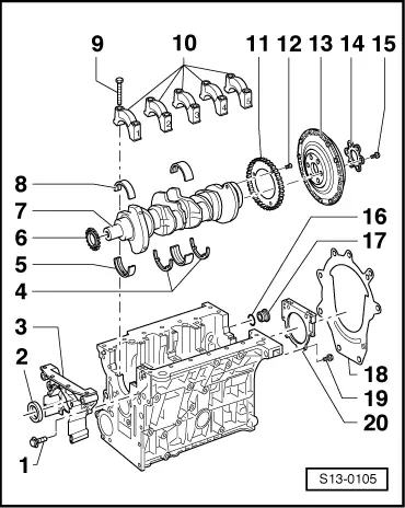
| Removing and installing crankshaft |

Note | t
| The engine should be attached to the engine repair stand with engine holder -MP 1-202- for carrying out removal and installation work. |
| –
| pay attention to different version → Fig. |
| –
| pay attention to different version |
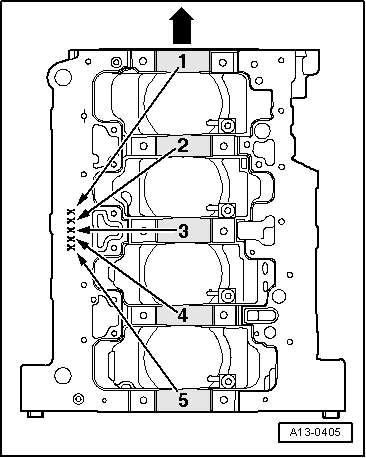
| –
| in bearing 3, for cylinder block or bearing cap |
| –
| lubricating grooves point outwards |
| –
| Identification for ordering replacement parts → Fig. |
| –
| for cylinder block with lubricating groove |
| –
| do not mix up used bearing shells (mark) |
| –
| Axial play when new: 0.07...0.21 mm |
| –
| Crankshaft bearing journal: Ø 54.00 mm |
| –
| Conrod bearing journal Ø 47.80 mm |
| –
| Identification for ordering replacement parts → Fig. |
| –
| for bearing cap without lubricating groove |
| –
| do not mix up used bearing shells (mark) |
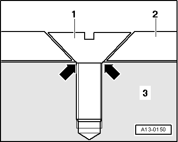
| 9 - | 40 Nm + torque a further 1/4 turn (90°) |
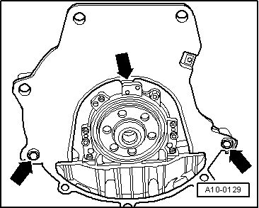
| –
| Bearing cover 1; on the belt pulley side |
| –
| Fitting position: retaining lugs of the bearing shells of the cylinder block/bearing cap must be on top of one another |
| –
| for engine speed sender -G28 - |
| –
| assembly only possible in one position -holes offset- |
| –
| Removing and installing sensor rotor → Fig. |
| 12 - | 10 Nm + torque a further 1/4 turn (90°) |
| 13 - | Pressure plate/driver disc |
| –
| Removing and installing pressure plate → Chapter |
| –
| removing and installing drive plate → Chapter |
| 15 - | 60 Nm + torque a further 1/4 turn (90°) |
| –
| inserted on sealing flange → Fig. |
| –
| must be positioned on dowel sleeves |
| –
| do not damage/bend during assembly work |
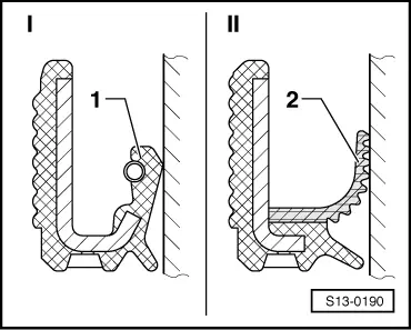
| 20 - | Rear sealing flange with gasket ring |
| –
| must be replaced completely |
| –
| must be positioned on dowel sleeves |
| –
| clean sealing surface before installing |
| –
| the sealing flange with PTFE gasket ring is supplied as a spare part |
| –
| install gasket ring dry, the crankshaft stub must be free of grease |
| –
| fit new sealing flange with guide bushing (do not pull guide bushing out of gasket ring before fitting) |
|
|
|