skoda Workshop Repair Guides

Skoda Workshop Service and Repair Manuals

1.6 ltr./55 kW Engine - 1 AVM fuel Injection and ignition system > < Testing knock sensor
Testing hall sender
Testing hall sender
Fitting location of the hall sender → Chapter.
Special tools and workshop equipment required
t  Handheld multimeter, e.g. -V.A.G 1526 A -
t  Measuring tool set -V.A.G 1594 A -
t  Test box -V.A.G 1598/22-
  Note
t  
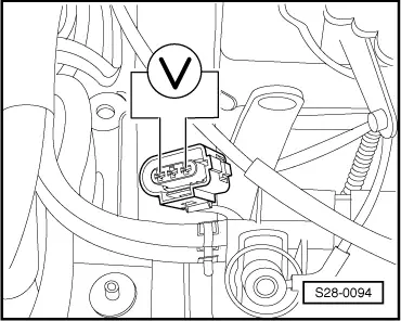
The hall sender is located below the camshaft wheel.
t  If the hall sender signal fails the cylinder assignment of the knock sensor signals is no longer possible, therefore the knock control is deactivated and the ignition angle is slightly reduced to avoid knocking effects.
t  If the hall sender signal fails the engine keeps running and can also be started again because of the following reasons:
t  There is no noticeable effect on the injection if there is a displacement of an engine revolution.
t  Instead of occurring with the injection valve open the injection occurs pre-engaged (before the closed injection valve). This only has a very slight influence on the quality of the mixture formation.
t  For the dual spark ignition system, an ignition spark is present for each engine revolution per cylinder and not only as usual for each second engine revolution.
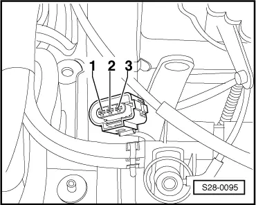
–  Disconnect plug at Hall sender.
–  Switch on ignition.
  Note
The female plugs are numbered correspondingly on the reverse side of the plug.
   
–  Connect the multimeter for voltage measurement to contact 1 (positive) and 3 (earth) of the plug for the Hall sender.
Specified value: 4.5 up to 5.5 V
–  Connect hand multimeter at contact 2 and 3 (earth) of the plug for the Hall sender.
Specified value: 4.5 up to 5.5 V
–  If the specified values are not reached, replace the Hall sender.
  Note
The voltage supply of the Hall sender is performed by the engine control unit.
–  If the specified values are not reached, test wiring from Hall sender to engine control unit as follows:
–  Switch off ignition.
–  Connect the test box -V.A.G 1598/22 - to the wiring loom of the engine control unit → Chapter.
  S28-0094
–  Test wiring of the Hall sender to the engine control unit for interruption as well as short-circuit to positive or earth.
For vehicles ► 07.97
  S28-0095
Contact at 3-pin plug of Hall senderBush to test box
1 (positive)62
2 (signal)76
3 (earth)67

For vehicles 08.97 ►
   
Contact at 3-pin plug of Hall senderBush to test box
1 (positive)62
2 (signal)76
3 (earth)70

For all vehicles
–  If the wiring is o.k however the voltages are not as described, replace the engine control unit → Chapter.
   

1.6 ltr./55 kW Engine - 1 AVM fuel Injection and ignition system > < Testing knock sensor