Octavia Mk1
 Note
Note
|
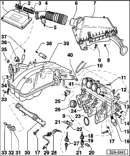
| 1 - | Control unit for Simos 2 -J361 -* |
| q | Fitting location: in plenum chamber |
| q | Checking voltage supply → Chapter |
| q | replace → Chapter |
| 2 - | Connector, 28 pin |
| q | Insert or remove plug when the ignition is switched off |
| q | unlock to remove |
| 3 - | Connector, 52 pin |
| q | Insert or remove plug when the ignition is switched off |
| q | unlock to remove |
| 4 - | Air intake hose |
| 5 - | To oil filler inlet |
| 6 - | Air mass meter -G70-* with intake air temperature sender - G42-* |
| q | up to model year 1997, the intake air temperature sender -G42- is a separate component part |
| q | Testing the air mass meter → Chapter |
| q | Test intake air temperature sender → Chapter |
| 7 - | Air filter |
| q | disassembling and assembling → Chapter |
| 8 - | 6 Nm |
| 9 - | 10 Nm |
| 10 - | Cable strap |
| q | for cable rail Pos. 41 |
| 11 - | 3 Nm |
| 12 - | Bottom part of intake manifold |
| 13 - | Feed line |
| q | secure with spring strap clamps |
| q | from fuel filter: → 1.6 ltr./74 Engine, Mechanics → Rep. Gr.20 |
| 14 - | Return-flow line |
| q | secure with spring strap clamps |
| q | to fuel delivery unit in fuel tank |
| 15 - | Fuel distributor |
| q | disassembling and assembling → Chapter |
| 16 - | Connector |
| q | 3-pin |
| q | for hall sender -G40- |
| 17 - | 15 Nm |
| 18 - | Connector |
| q | 4-pin |
| q | for coolant temperature sender - G62- |
| q | Contacts 1 and 3 gilded |
| 19 - | Coolant temperature sender -G62-* |
| q | blue |
| q | for engine control unit |
| q | with coolant temperature gauge sensor -G2- |
| q | check → Chapter |
| q | before removing, reduce pressure in cooling system if necessary |
| 20 - | Split pin |
| q | check tightness |
| 21 - | O-ring |
| q | replace if damaged |
| 22 - | Engine speed sender -G28-* |
| q | check → Chapter |
| 23 - | Gasket ring |
| q | replace |
| 24 - | Connector |
| q | black, 2 pin |
| q | for injection valves (-N30-...N33) |
| 25 - | Connector |
| q | black, 2 pin |
| q | for variable intake manifold changeover valve -N156- |
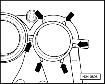
| 26 - | Gasket ring |
| if no stops are present for correct gasket ring position at the bottom part of the intake manifold: |
| q | Stick gasket ring with glue -D 000 801- and hardener -D 000 802- to the bottom part of the intake manifold. |
| q | Fitting position: → Fig. |
| 27 - | 3-pin connector |
| q | grey |
| q | for engine speed sender |
| q | Fitting location → Chapter |
| 28 - | 4-pin connector |
| q | black |
| q | for lambda probe and heating for lambda probe |
| q | Contacts 3 and 4 gilded |
| q | Fitting location → Chapter |
| 29 - | Lambda probe -G39-* 50 Nm |
| q | grease the thread with “G 052 112 A3”; “G 052 112 A3” must not get into the slots of the probe body |
| q | Checking lambda control → Chapter |
| q | Voltage supply of the heating for lambda probe via fuel pump relay -J17- |
| q | Check heating for lambda probe → Chapter |
| q | Fitting location → Chapter |
| 30 - | Support |
| q | between intake manifold and cylinder head |
| 31 - | Rubber bush |
| 32 - | Washer |
| 33 - | 8 Nm |
| 34 - | to heat exchanger |
| 35 - | from the expansion reservoir |
| 36 - | Connector |
| q | 8-pin |
| q | contacts gold-plated |
| q | for throttle valve control unit -J338- |
| 37 - | to activated charcoal filter system solenoid valve 1 -N80-** |
| q | Activated charcoal filter system: → 1.6 ltr./74 kW Engine, Mechanics → Rep. Gr.20 |
| 38 - | To the brake servo unit |
| 39 - | Top part of intake manifold |
| q | with variable intake manifold changeover |
| q | disassembling and assembling → Chapter |
| 40 - | Body-bound rivet |
| 41 - | Cable rail |