| –
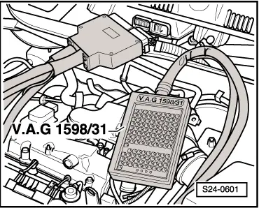
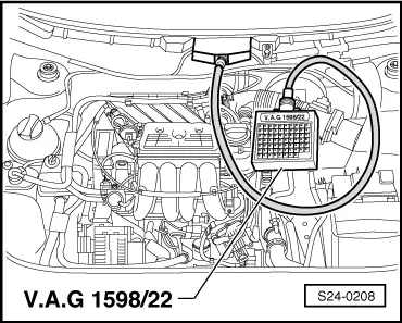
| Connect test box -V.A.G 1598/22- to connector of wiring loom. |
| –
| Perform test as described in the relevant repair sequences. |

WARNING | To avoid damaging the electronic components, switch on the relevant measuring range before connecting the measuring cables and comply with the test conditions. |
|

Note | After re-connecting the engine control unit perform adaptation of the engine control unit to the throttle valve control unit → Chapter. |
| For engine with engine identification characters ARZ, ARX, AUM |
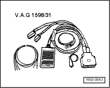
| Special tools, test equipment as well as aids required |
|
|
|