skoda Workshop Repair Guides

Skoda Workshop Service and Repair Manuals

Testing the intake system for tightness (unmetered air) > < Testing the fuel pressure regulator and holding pressure (pressure in system)
Inspecting the injection rate, tightness and jet formation of the injectors
Special tools, test equipment as well as aids required
t  Vehicle system tester -V.A.G 1552- with cable -V.A.G 1551/3-, 3A, 3B or 3C
t  Measuring tool set, e.g. -V.A.G 1594 A-, B or C
t  
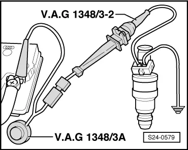
Remote control -V.A.G 1348/3A- with adapter cable -V.A.G 1348/3-2-
t  Measuring cylinder, e.g. -V.A.G 1602-
Test condition
l  Fuel pressure o.k., test → Chapter
l  Fuel pump relay OK → Current flow diagrams and Fitting locations
l  Fuel temperature 15...20 °C, fuel must according to the valid standards
Method:
–  Unplug connectors at all the injectors.
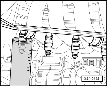
–  Remove the complete fuel rail.
–  Detach vacuum hose from fuel pressure regulator.
–  Remove fuel rail together with injectors from intake manifold and support.
Check tightness
–  Connect vehicle system tester -V.A.G 1552-. Switch ignition on and select address word 01 “Engine electronics” → Chapter.
–  Initiate final control diagnosis and drive injector cyl. 1 activate, the fuel pump must run.
  Note
This sequence is intended to ensure that the fuel pump runs when the engine is switched off. The idling speed limit switch must be in closed position as otherwise the selected injector will spray five times.
–  Test the tightness of the injectors (visual inspection). With the fuel pump running per valve only 1...2 drops of fuel may escape per minute.
–  If the fuel loss is greater adjust the fuel pump (end final control diagnosis) and replace defective injector.
  Note
Replace seals at the same time.
–  If necessary repeat final control diagnosis.
  Note
The final control diagnosis can only be initiated again once the ignition has been briefly switched off.
Testing injection rate
  Note
When testing the injection rate also check the jet formation. The jet must be the same for all injection valves.
   
–  Insert injector to be tested in a measuring glass.
–  Connect one contact of injector to earth.
  S24-0152
–  Connect the second contact of the injector to the remote control.
–  Connect terminal to battery positive (+).
  S24-0579
–  Connect battery positive (+) and fuse socket No. 28 with -V.A.G 1348/3-2 -.
The fuel delivery unit must start running.
–  Operate remote control for 30 seconds.
–  Perform the measurement on all injectors.
–  Once all four injectors have been driven, position the graduated measuring glasses on an even base.
–  Switch off voltage supply of fuel delivery unit.
–  Compare the individual quantities of fuel injected.
For engine with engine identification characters AGU
Specified value: 124...134 ml
For engine with engine identification characters ARZ, ARX, AUM
Specified value: 139...150 ml
Continued for all engines
–  If the measured value of one or more injectors is outside the tolerance, replace the defective injector → Chapter.
Pay attention to the following points before fitting the injectors:
l  Replace O-rings on all opened connecting points (to replace the front O-ring do not remove the plastic valve head cap - place the O-ring over the plastic cap).
l  Moisten O-rings with clean engine oil.
l  Pay attention to correct positioning of the injectors.
l  Check perfect fit of the retaining clips.
–  Installation occurs in reverse order.
  S20-0182

Testing the intake system for tightness (unmetered air) > < Testing the fuel pressure regulator and holding pressure (pressure in system)