skoda Workshop Repair Guides

Skoda Workshop Service and Repair Manuals

Fault table > < Procedure
Actuator diagnosis
Actuator diagnosis
Test conditions
   
l  
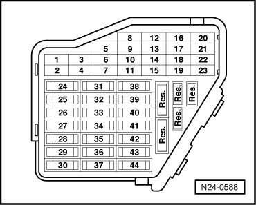
Fuses No. 10, 28, 29, 32, 34 and 43 OK.
Special tools, test equipment as well as aids required
t  Vehicle system tester -V.A.G 1552- with cable -V.A.G 1551/3-, 3A, 3B or 3C
  Note
t  The actuator diagnosis can only be carried out when the engine is not running and the ignition is switched on.
t  The final control diagnosis is aborted when the engine is started or when a moment of momentum is detected.
t  During the actuator diagnosis the individual actuators remain activated until the next actuator is selected by pressing key .
t  The actuators are tested acoustically or by touch.
t  Before repeating final control diagnosis without briefly running the engine, switch the ignition off for about 2 seconds.
t  The electric fuel pump runs during the entire final control diagnosis.
t  Final control diagnosis is aborted after 10 minutes.
t  The idling switch must be OK.
For engine with engine identification characters AGU
With the actuator diagnosis the following parts are activated in the sequence indicated:
  N24-0588
1.Injection valve for cylinder 1 -N30-
2.Injection valve for cylinder 2 -N31-
3.Injection valve for cylinder 3 -N32-
4.Injection valve for cylinder 4 -N33-
5.Solenoid valve 1 for activated charcoal filter -N80-
6.Solenoid valve for charge pressure control -N75-

Procedure
–  Connect vehicle system tester -V.A.G 1552- and select engine electronics control unit (address word 01) → Chapter. The ignition must be switched on for this purpose.
–  Enter 03 for the function “Actuator diagnosis”.
   
Confirm entry with key Q.
Injection valve:
 
Vehicle system test                   Q
03 - Actuator diagnosis
Readout on display:
–  Open throttle valve. As soon as the idling switch opens, the injector for cylinder 1 clicks five times.
–  If you want to switch to the next injector press key . (Switching can also be performed without testing the relevant injector).
–  Test all the injectors one after the other in this way.
If one of the injectors is not actuated (does not click):
–  Test resistance of valve → Chapter.
–  Check wires to valve for short-circuit or open circuit → Current flow diagrams and Fitting locations.
–  Press key.
Activated charcoal filter system solenoid valve 1 -N80-
 
Actuator diagnosis                    ->
Injector cyl. 1 N30
Fitting position of the solenoid valve -2-.
  S24-0176
The solenoid valve (in front of the coolant expansion reservoir) must click.
If the injector is not actuated (does not click):
–  Test resistance of valve → Chapter.
–  Check wires to valve for short-circuit or open circuit → Current flow diagrams and Fitting locations.
If the solenoid valve clicks, opens and closes:
–  Press key.
Solenoid valve for charge pressure control -N75 -:
 
Actuator diagnosis                    ->
Solenoid valve 1 for activated charcoal filter system N80
This valve must be actuated (clicked), until the final control diagnosis is ended by pressing the key.
If the injector is not actuated (does not click):
–  Test resistance of valve → Chapter.
–  Check wires to valve for short-circuit or open circuit → Current flow diagrams and Fitting locations.
–  End output and switch off ignition.
  Note
Before the function 03 of the “final control diagnosis” is selected again, the ignition must be switched off for approximately 20 secs. If you do not switch off the ignition before again starting the engine, the starter turns the engine, but the engine will not start as the injectors and the ignition transformer will not be operated.
For engine with engine identification characters ARZ, ARX, AUM
With the actuator diagnosis the following parts are activated in the sequence indicated:
 
Actuator diagnosis                    ->
Solenoid valve for charge pressure control.  N75
1.Solenoid valve 1 for activated charcoal filter -N80-
2.Secondary air injection valve -N112-
3.Secondary air pump relay -J299-
4.Solenoid valve for charge pressure control -N75-
5. → NoteCamshaft adjustment
6.Turbocharger divert air valve -N249-
7. → NoteBrake vacuum pump
8.Injection valve for cylinder 1 -N30-
9.Injection valve for cylinder 3 -N32-
10.Injection valve for cylinder 4 -N33-
11.Injection valve for cylinder 2 -N31-

1)  For engine with engine identification characters ARX, AUM.
2)  For models with automatic gearbox. The designation of the diagnosis can also be displayed as “Information in the literature”
Procedure
–  Connect vehicle system tester -V.A.G 1552-. Switch ignition on and select address word 01 “Engine electronics” → Chapter.
   
Enter 03 for the function “Actuator diagnosis”.
 
Vehicle system test                 HELP
Select function XX
Confirm the entry with the key Q.
Activated charcoal filter system solenoid valve 1 -N80-
 
Vehicle system test                   Q
03 - Actuator diagnosis
This solenoid valve (in front of the coolant expansion reservoir) must click.
If the injector is not actuated (does not click):
–  Test resistance of valve → Chapter.
–  Check wires to valve for short-circuit or open circuit → Current flow diagrams and Fitting locations.
If the solenoid valve clicks, opens and closes:
–  Press key.
Secondary air injection valve -N112-:
 
Actuator diagnosis                    ->
Tank vent valve N80
The secondary air injection valve -N112- must click, until the key is pressed.
If the injector is not actuated (does not click):
–  Inspect valve power supply.
–  Check wires to valve for short-circuit or open circuit → Current flow diagrams and Fitting locations.
–  Press key.
Secondary air pump relay -J299 -:
The installation position for secondary air pump relay - J299- in holder in protective housing next to brake servo unit.
–  Test fuse for secondary air pump relay -J299 -.
 
Actuator diagnosis                    ->
Secondary air inlet valve N112
The secondary air pump relay -J299- is controlled by the secondary air pump motor, the motor runs at intervals until key is pressed.
–  If the secondary air pump motor does not run at intervals, check the secondary air pump motor → Current flow diagrams and Fitting locations.
–  Press key.
Solenoid valve for charge pressure control -N75 -:
 
Actuator diagnosis                    ->
Secondary air pump relay J299
This valve is actuated (clicks), until key is pressed.
If the injector is not actuated (does not click):
–  Test resistance of valve → Chapter.
–  Check wires to valve for short-circuit or open circuit → Current flow diagrams and Fitting locations.
–  Press key.
Camshaft adjustment:
 
Actuator diagnosis                    ->
Solenoid valve for charge pressure control. N75
This valve is actuated (clicks), until key is pressed.
If the injector is not actuated (does not click):
–  Test resistance of valve → Chapter.
–  Check wires to valve for short-circuit or open circuit → Current flow diagrams and Fitting locations.
–  Press key.
Turbocharger divert air valve -N249-:
 
Actuator diagnosis                    ->
Camshaft adjustment
This valve is actuated (clicks), until key is pressed.
If the injector is not actuated (does not click):
–  Inspect valve power supply.
–  Check wires to valve for short-circuit or open circuit → Current flow diagrams and Fitting locations.
–  Press key.
Activate brake vacuum pump
(Only for vehicles with automatic gearbox)
 
Actuator diagnosis                    ->
Turbocharger divert air valve N249
The vacuum pump for brake booster runs at intervals, until the key is pressed.
–  If the vacuum pump for brake booster does not run at intervals, check: → Running Gear; Rep. Gr.47.
–  Press key.
Injection valve:
 
Actuator diagnosis                    ->
Brake vacuum pump
Injector valve for cylinder 1 clicks repeatedly.
–  If you want to switch to the next injector press key . (Switching can also be performed without testing the relevant injector).
–  Test all the injectors one after the other in this way.
If one of the injectors is not actuated (does not click):
–  Test resistance of valve → Chapter.
–  Check wires to valve for short-circuit or open circuit → Current flow diagrams and Fitting locations.
–  Press key.
 
Actuator diagnosis                    ->
Injector cyl. 1 N30
Readout on display:
–  End output and switch off ignition.
 
Actuator diagnosis                    ->
END

Fault table > < Procedure