skoda Workshop Repair Guides

Skoda Workshop Service and Repair Manuals

Removing and installing sealing flange and flywheel > < Removing and installing V-ribbed belt
Removing and installing, tightening the timing belt
  Note
Before removing the timing belt, mark direction of running. Reversing the rotation direction of an already used belt may destroy it.
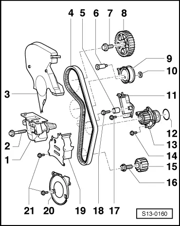
1 - Engine support bracket
2 - 45 Nm
3 - Top toothed belt guard
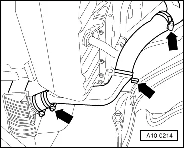
–  to remove, if necessary unscrew bracket for coolant return-flow line to exhaust turbocharger
4 - Timing belt
–  before removing mark running direction
–  check for wear
–  do not kink
–  removing → Anchor
–  Install and tension → Anchor
5 - Guide pulley
6 - 27 Nm
7 - 65 Nm
–  to release and tighten use the counterholder -MP 1-216-
8 - Camshaft sprocket
–  for exhaust camshaft
–  for removing and installing, remove toothed belt → Anchor
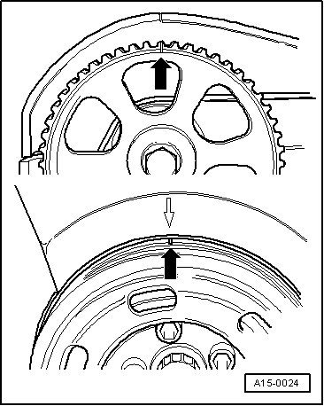
–  check fitting position: the small stay on the camshaft sprocket points outwards and the TDC marking on the cylinder 1 is visible
9 - Tensioning pulley
10 - Washer
11 - Tensioning device for timing belt
12 - O-ring
–  replace, moisten with coolant when installing
13 - Coolant pump
–  removing and installing → Chapter
14 - 15 Nm
15 - Timing belt gear - crankshaft
–  there must not be any oil present on contact surface between timing belt sprocket and the crankshaft
–  can be installed only in one position
16 - 90 Nm + torque a further 1/4 turn (90°)
–  replace
–  to release and tighten the counterholder -MP 1-310- or -T30004- use
–  when bolting on counter-holder -MP 1-310-, place 2 washers between timing belt sprocket and counter-holder
17 - 15 Nm
18 - 20 Nm
19 - Middle toothed belt guard
20 - Bottom toothed belt guard
21 - 10 Nm
Special tools and workshop equipment required
t  Torque wrench
t  
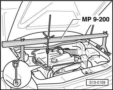
Supporting device -MP 9-200-
t  
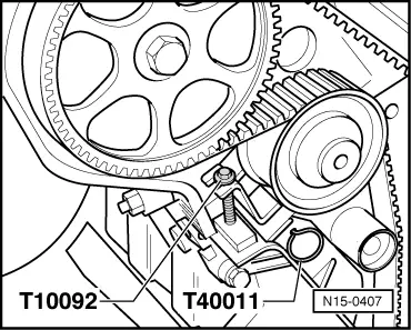
Locking pin e. g. -T40011-
t  Clamp bolt -T10092-
Removing toothed belt
l  Engine installed.
–  Remove the V-ribbed belt and clamping fixture → Anchor.
–  Disconnect plug at coolant expansion reservoir and at activated charcoal filter system solanoid valve.
–  Unbolt the coolant expansion reservoir and the PAS reservoir, hoses remain connected.
–  Detach the vacuum line from the ACF reservoir and from the throttle valve support.
–  Remove top toothed belt guard.
  S13-0160
–  Fit supporting device -MP 9-200-.
–  Slightly raise the engine using the spindle on the catching device -MP 9-200-.
  Note
Tie up the coolant expansion reservoir and the PAS reservoir at the supporting device.
–  Remove noise insulation and right engine cover.
  S13-0159
–  Remove the air guide pipe between the exhaust turbocharger and the charge air cooler -arrows-.
–  Unclip the line for the vane pump on the power-assisted steering from the supports at the engine and the body.
  A10-0214
–  Position crankshaft in direction of rotation of engine to TDC marking of cylinder 1 -arrows-.
  A15-0024
–  Check, if TDC marking on flywheel and reference mark are aligned -arrow-.
I - Gearbox
II - Automatic gearbox
–  Remove engine mount and engine support bracket.
–  Remove the vibration damper without altering the TDC position.
–  Remove bottom and middle timing belt guard.
–  Mark the direction of rotation of the timing belt with chalk or a felt-tip pen.
  S13-0164
–  Screw the - T10092- clamp bolt into the tensioning device for the toothed belt.
–  Tension pressure piston of tensioning device just sufficiently to enable the pressure piston to be secured with a locking pin (e.g. -T40011 -).
–  Remove timing belt.
Installing toothed belt, tensioning
  Note
t  Also when carrying out repairs which necessitate taking the toothed belt only off the camshaft sprocket, it is then necessary to carry out the setting of the toothed belt as follows.
t  When rotating the camshaft, the crankshaft must not be positioned at TDC. Risk of damaging valves and pistons.
  N15-0407
–  Bring the marking on the camshaft sprocket in line with the marking on the cylinder head cover (TDC cyl. 1).
–  Fit timing belt onto the timing belt gear crankshaft (pay attention to direction of running).
–  Install bottom timing belt guard.
Tightening torque: 10 Nm
–  Install vibration damper (pay attention to fitting position: Hole of the vibration damper is above the lobe on the timing belt sprocket).
Tightening torque: 40 Nm
–  Bring the marking on the vibration damper in line with the marking on the bottom part of toothed belt guard (TDC cyl. 1).
  A15-0024
–  Check, if TDC marking on flywheel and reference mark are aligned -arrow-.
I - Gearbox
II - Automatic gearbox
–  Fit timing belt in the order cooling pump, tensioning pulley, camshaft sprocket.
  S13-0164
–  Pull out rig pin and slacken pressure piston of tensioning device for toothed belt. Screw out -T10092- the tensioning screw.
–  Turn the crankshaft twice in the running direction of the engine, position again on TDC and check the setting.
–  Install middle timing belt guard.
   Tightening torque: 10 Nm
–  Install engine support → Anchor, position 1.
–  Install engine mount → Chapter.
–  Remove the supporting device -MP 9-200-.
–  Install top toothed belt guard.
–  Install the V-ribbed belt and clamping fixture → Anchor.
–  Tighten coolant expansion reservoir and PAS reservoir.
   Tightening torque: 10 Nm
  Note
Connecting and disconnecting plug connections causes faults to be stored in the engine control unit. It is therefore necessary to interrogate the fault memory → 1.8 l/110 kW Engine, Fuel Injection and Ignition System Motronic; Rep. Gr.01.
  N15-0407

Removing and installing sealing flange and flywheel > < Removing and installing V-ribbed belt