skoda Workshop Repair Guides

Skoda Workshop Service and Repair Manuals

Testing knock sensors > < Ignition system - technical data
Check dual spark ignition system with two ignition coils
Special tools and workshop equipment required
t  Voltage tester (e.g. - V.A.G 1527-)
t  Test box -V.A.G 1598/22-
t  Handheld multimeter (e.g. -V.A.G 1526 A-)
t  Measuring tool set (e.g. -V.A.G 1594 A-)
t  Current flow diagram
Test conditions
l  Battery voltage at least 11.5 volts
l  Engine speed sender o.k., test → Chapter
l  Hall sender o.k., test → Chapter
Check the earth distribution of the power output stage
  Note
Ignition coils and power amplifier are a common component and cannot be replaced individually.
   
–  Unplug 4-pin connector -1- from the ignition coils -2-.
  S28-0074
–  Connect voltage tester (earth), voltage tester must light up.
–  If the voltage tester does not light up, check wiring according to current flow diagram and if necessary correct open ciruit → Current Flow Diagrams, Electrical Fault Finding and Fitting Locations.
Check voltage supply of the ignition coils
Inspection requirement:
  S28-0076
l  Fuse 29 for ignition coils o.k.
–  Unplug 4-pin connector from the ignition coils.
–  Switch on ignition.
  N24-0588
–  Connect voltage tester -V.A.G 1527- between engine mass and contact 2 of the plug (positive).
Specified value: The voltage tester must light up.
–  If the specified values are not reached, test the line interruption according to the current flow diagram, if necessary repair or test the fuse → Current Flow Diagrams, Electrical Fault Finding, Fitting Locations.
Test control
–  Unplug connectors from all four injectors.
–  Switch on ignition.
–  Voltage tester -V.A.G 1527- between engine mass and consecutively to contact 1 and 3.
–  Operate starter for some seconds. While doing so the voltage tester must flash.
–  Connect test box -V.A.G 1598/22 - at wiring loom to the engine control unit → Chapter.
  S28-0075
–  If the voltage tester does not flash, check the wiring from plug for engine control unit for continuity or short circuit according to the current flow diagram (connect the test box -V.A.G 1598/22- to the wiring loom on the engine control unit).
–  If necessary eliminate wire interruption or short-circuit.
  S24-0148
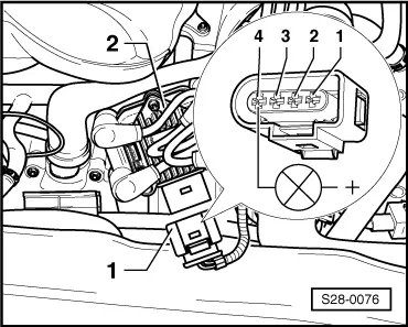
Contact at 4-pin plug of power output stageContact at control unit plug
171
378

–  If no open circuit or earth was detected, replace the engine control unit → Chapter.
   

Testing knock sensors > < Ignition system - technical data