
Octavia Mk1
 Note
Note
|
| Valid ? 07.97 |
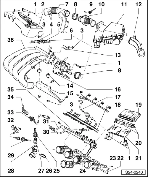
| 1 - | M6 = 10 Nm, M8 = 20 Nm |
| 2 - | Ignition lead guide |
| 3 - | 25 Nm |
| 4 - | Connector |
| q | black, 2 pin |
| q | for intake air temperature sender -G42 - |
| 5 - | Intake air temperature sender - G42-* |
| 6 - | O-ring |
| q | replace if damaged |
| 7 - | Air intake hose |
| 8 - | Warm-type clamp |
| 9 - | Connector |
| q | 3-pin |
| q | for air mass meter -G70- |
| 10 - | Air mass meter -G70-* |
| 11 - | Air filter |
| q | disassembling and assembling → Chapter |
| 12 - | Induction pipe |
| 13 - | Support |
| q | for throttle control cable |
| 14 - | Rubber top mount |
| 15 - | Support |
| q | for intake manifold, at cylinder head with screw thread |
| 16 - | Throttle valve control unit -J338-* |
| 17 - | Vacuum hose |
| q | to top part of the intake manifold |
| 18 - | Cable guide |
| q | clipped on to fuel rail |
| 19 - | Motronic control unit -J220-* |
| q | for injection system, lambda regulation, camshaft adjustment valve, activated charcoal filter system solenoid valve, knocking regulation, speed limiter, ignition as well as self-diagnosis |
| q | Fitting location: at centre of plenum chamber |
| q | Check supply voltage → Chapter |
| q | when replacing, perform adaptation to the throttle valve control unit → Chapter |
| q | when replacing, perform adaptation to the electronic immobiliser → Chapter |
| 20 - | Connector |
| q | insert or remove plug when the ignition is switched off |
| q | unlock to remove |
| 21 - | Fixing plate |
| 22 - | Gasket |
| q | replace |
| 23 - | 10 Nm |
| 24 - | Bottom part of intake manifold |
| q | disassembling and assembling → Chapter |
| 25 - | Connector |
| q | 4-pin |
| q | Cable of socket 1 and cable of socket 3 for -G62- |
| 26 - | Retaining clip |
| 27 - | Coolant temperature sender - G62-* |
| q | with coolant temperature gauge sensor -G2- |
| q | Identification: yellow ring |
| q | before removing, reduce pressure in cooling system if necessary |
| q | check → Chapter |
| 28 - | O-ring |
| q | replace if damaged |
| 29 - | 3-pin plug connection |
| q | for engine speed sender -G28- |
| 30 - | Fuel feed line |
| q | secure hose with spring strap clip |
| q | hose with a white marking |
| 31 - | Fuel return-flow line |
| q | secure hose with spring strap clip |
| q | hose with a blue marking |
| 32 - | Engine speed sender -G28-* |
| q | Fitting location: Cylinder-block intake side |
| q | check → Chapter |
| 33 - | Lambda probe -G39-*, 55 Nm |
| q | Fitting location: exhaust tube front |
| q | Only grease the thread with -G5-; -G5- must not come into contact with the slots of the probe body |
| q | Test lambda probe and lambda control → Chapter |
| q | Power supply of probe heating via fuel pump relay - J17- |
| q | Check lambda probe heater → Chapter |
| 34 - | 4-pin plug connection |
| q | for lambda probe -G39- and heating for lambda probe -Z19- |
| q | attached to the vehicle floor on the right next to the lambda probe below a cap |
| 35 - | Fuel rail with injection valves */** |
| 36 - | Top part of intake manifold |
| disassembling and assembling → Anchor |
| Valid 08.97 ? |

| 1 - | 10 Nm |
| 2 - | Intake manifold cover |
| 3 - | 20 Nm |
| 4 - | Rubber top mount |
| 5 - | Support |
| q | for intake manifold, at cylinder head with screw thread |
| 6 - | 25 Nm |
| 7 - | Air intake hose |
| 8 - | Warm-type clamp |
| 9 - | Connector |
| q | 5-pin |
| q | for air mass meter -G70- and intake air temperature sender -G42- |
| 10 - | Air mass meter -G70-* and intake air temperature sender -G42-* |
| 11 - | Air filter |
| q | disassembling and assembling → Chapter |
| 12 - | Induction pipe |
| 13 - | Fuel pressure regulator |
| 14 - | Throttle valve control unit -J338-* |
| 15 - | Non-return valve |
| q | for vacuum reservoir, which is integrated into the intake manifold |
| q | pay attention to correct fitting position; the valve does not function if it is incorrectly assembled, otherwise reduced acceleration |
| 16 - | Shift linkage |
| q | for variable intake manifold changeover |
| 17 - | Vacuum unit |
| q | for variable intake manifold changeover |
| 18 - | Fuel rail with injection valves */** |
| 19 - | Motronic control unit -J220-* |
| q | for injection system, lambda regulation, camshaft adjustment valve, activated charcoal filter system solenoid valve, knocking regulation, speed limiter, ignition as well as self-diagnosis |
| q | Fitting location: at centre of plenum chamber |
| q | Checking voltage supply → Chapter |
| q | when replacing, perform adaptation to the throttle valve control unit → Chapter |
| q | when replacing, perform adaptation to the electronic immobiliser → Chapter |
| 20 - | Connector |
| q | insert or remove plug when the ignition is switched off |
| q | unlock to remove |
| 21 - | Fixing plate |
| 22 - | 10 Nm |
| 23 - | Plug connection fuse |
| q | for connector for injection valves |
| 24 - | Connector |
| q | for hall sender -G40- |
| 25 - | Connector |
| q | for injection valves -N30- to -N33- |
| 26 - | Bottom part of intake manifold |
| q | disassembling and assembling → Chapter |
| 27 - | Coolant temperature sender - G62-* |
| q | with coolant temperature gauge sensor -G2- |
| q | Identification: yellow ring |
| q | before removing, reduce pressure in cooling system if necessary |
| q | check → Chapter |
| 28 - | Retaining clip |
| 29 - | Connector |
| q | 4-pin |
| q | Cable for -G62- in socket 1 and 3 |
| 30 - | 3-pin plug connection |
| q | for engine speed sender -G28- |
| 31 - | Engine speed sender -G28-* |
| q | Fitting location: Cylinder-block intake side |
| q | check → Chapter |
| 32 - | Lambda probe -G39-*, 55 Nm |
| q | Fitting location: exhaust tube front |
| q | Only grease the thread with -G5-; - G5- must not come into contact with the slots of the probe body |
| q | Test lambda probe and lambda control → Chapter |
| q | Power supply of probe heating via fuel pump relay -J17- |
| q | Check lambda probe heater → Chapter |
| 33 - | 4-pin plug connection |
| q | for lambda probe -G39- and heating for lambda probe -Z19- |
| q | attached to the vehicle floor on the right next to the lambda probe below a cap |
| 34 - | Cable guide |
| q | screwed on with fuel distributor at bottom part of the intake manifold |
| 35 - | Lock catches |
| q | for shift linkage of variable intake manifold changeover |
| 36 - | Valve for variable intake manifold changeover -N156- |
| 37 - | Connector |
| q | for variable intake manifold changeover valve -N156- |
| 38 - | Top part of intake manifold |
| q | disassembling and assembling → Chapter |