skoda Workshop Repair Guides

Skoda Workshop Service and Repair Manuals

Testing clutch pedal switch F36 > < Test sequence
Test brake light switchF and brake pedal switchF47
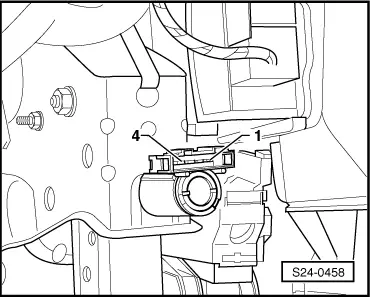
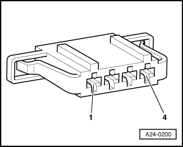
Test brake light switch -F- and brake pedal switch -F47-
As the injection system operates with an accelerator pedal position sender (potentiometer), which may become defective, for reasons of safety the engine is cut-off when the brake is activated. To do so the brake light switch signal and additionally the brake pedal swicth signal in the engine control unit -J248- is required.
If the brake pedal is activated simultaneously with the accelerator pedal pressed, the engine immediately slows down to idling speed. A defective brake pedal switch may result in involuntary cut-off procedures.
Special tools and workshop equipment required
t  Vehicle system tester -V.A.G 1552-
t  Diagnostic cable -V.A.G 1551/3- or -V.A.G 1551/3A- or -V.A.G 1551/3B-
t  Hand multimeter (e.g. -V.A.G 1526 A-)
t  Adapter cable set (e.g. -V.A.G 1594 A-)
t  Test box -V.A.G 1598/31-
Test condition
l  Fuses no. 13 and no. 43 o.k.
Check for proper operation
–  Connect vehicle system tester -V.A.G 1552-. Switch ignition on and then select “address word” 01 Engine electronics → Chapter.
–  Select function 08 “read measured value block” and display group number 006.
   
Readout on display:
–  Observe the display in display field 2.
   Specified value:
   X00 (if brake pedal not pressed)
   X11 (if brake pedal pressed)
–  Select function 06 “End output” and confirm with Q.
–  Switch off ignition.
–  If the display does not occur as described:
Testing switch
–  Remove lower part of the dash panel insert on the driver's side → Body Work; Rep. Gr.70.
–  Remove the left footwell blower.
–  Unplug the plug at the brake light/brake pedal switch.
 
Reading measured value block         6   ->
0 km/h       000         0 %          0
–  Connect handheld multimeter for resistance measurement between contact 1 and 4.
   Specified value: ∞ Ω (no continuity)
–  Actuate brake pedal.
   Specified value: max. 1.5 Ω
  S24-0458
–  Connect handheld multimeter for resistance measurement between contact 2 and 3.
   Specified value: max. 1.5 Ω
–  Actuate brake pedal.
   Specified value: ∞ Ω (no continuity)
If the specified values are not reached:
–  Replace brake light/brake pedal switch.
If the specified values are reached:
Checking voltage supply
  S24-0458
–  Connect handheld multimeter for voltage measurement as follows:
  A24-0200
Plug connection contactSpecification
1 + earthapprox. battery voltage

–  Switch on ignition.
   
Plug connection contactSpecification
2 + earthapprox. battery voltage

If the specified values are not reached:
–  Check the cable between contact 1 of the plug and fuse 2 according to the current flow diagram for interruption → Current flow diagrams and Fitting locations.
–  Check the cable between contact 2 of the plug and fuse 28 according to the current flow diagram for interruption → Current flow diagrams and Fitting locations.
If the specified values are reached:
Testing the wiring
–  Switch off ignition.
–  Connect test box -V.A.G 1598/31- to the wiring loom on the engine control unit → Chapter.
   
–  Check the following wire for interruption or short-circuit to earth or positive:
  A24-0200
Plug connection contactTest box -V.A.G 1598/31-, bush 
365 
432

–  If necessary eliminate wire interruption or short-circuit.
   

Testing clutch pedal switch F36 > < Test sequence