skoda Workshop Repair Guides

Skoda Workshop Service and Repair Manuals

Testing Fuel temperature sender G81 > < Testing Engine speed sender G28
Testing Intake manifold pressure senderG71 and Altitude senderF96
Testing Intake manifold pressure sender -G71- and Altitude sender -F96-
1)  The altitude sender -F96- is located in the engine control unit. The intake manifold pressure sender -G71- is a separate component and is located together with the intake manifold temperature sender -G72- in the intake mainfold in a common housing on the charge-air cooler.
Special tools and workshop equipment required
t  Vehicle system tester -V.A.G 1552-
t  Diagnostic cable -V.A.G 1551/3, 3A, 3B oder 3C-
t  Hand multimeter (e.g. -V.A.G 1526 A-)
t  Adapter cable set (e.g. -V.A.G 1594 C-)
t  Test box -V.A.G 1598/31-
t  Barometer
Test sequence
–  Connect vehicle system tester -V.A.G 1552-. Switch ignition on and select address word 01 “Engine electronics” → Chapter.
–  Select function 08 “Read measured value block” and display group number 010.
   
–  Compare the displays in display field 2 (altitude sender - F96-) and in display field 3 (intake manifold pressure sender -G71-) with the display on the barometer.
   Specified value: the pressures must correspond (±30 mbar)
  Note
The display on the barometer serves as comparative value.
If the value in display field 2 is different:
–  Select function 06 “End output” and confirm with Q.
–  Switch off ignition.
–  Replacing engine control unit -J248- → Chapter.
If the value in display field 3 is different:
–  Select function 06 “End output” and confirm with Q.
–  Start the engine and select function 08 “Read measured value block” and display group number 010.
  Note
In order to disconnect the plug on the intake manifold pressure sender - G71- it is necessary to remove the right headlight → Electrical System; Rep. Gr.94.
 
Reading measured value block         10   ->
0 mg/stroke  989.mbar  999.mbar 0.0 %
–  Disconnect plug -1- at intake manifold pressure sender -G71--2-.
  S23-0118
–  Observe the values shown in indicator fields 2 and 3.
Values must fall steadily.
If the specified value is reached:
–  Select function 06 “End output” and confirm with Q.
–  Switch off ignition.
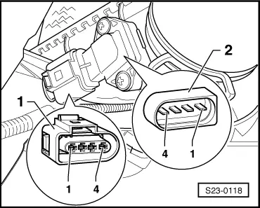
–  Replace the intake manifold pressure sender -G71- with intake manifold temperature sender -G72-.
If the specified value is not reached:
–  Select function 06 “End output” and confirm with Q.
–  Switch off ignition.
–  Connect test box -V.A.G 1598/31- to the wiring loom on the engine control unit → Chapter.
 
Reading measured value block         10   ->
0 mg/stroke  989.mbar  999.mbar 0.0 %
–  Check the following wire for interruption or short-circuit to earth or positive:
  S23-0118
Connector -1-,
contact
Test box -V.A.G 1598/31-, bush 
152 
331
471

–  Also check the wires for short-circuits.
If the lines are not found to be faulty:
–  Replacing engine control unit -J248- → Chapter.
   

Testing Fuel temperature sender G81 > < Testing Engine speed sender G28