
Octavia Mk1

| 1 - | 120 Nm + torque a further (90°) 1/4 turn |
| q | to release and tighten the counterholder -MP 1-310- or counterholder -T30004- use |
| q | always replace |
| q | thread and contact surface must be free of oil and grease. |
| q | tightening to 90° may occur in successive stages |
| 2 - | 40 Nm + torque a further (90°) 1/4 turn |
| q | always replace |
| q | tightening to 90° may occur in successive stages |
| 3 - | 15 Nm |
| 4 - | 23 Nm |
| 5 - | 22 Nm |
| q | for vehicles 03.00 ? |
| 6 - | Bottom toothed belt guard |
| 7 - | 10 Nm |
| 8 - | Middle toothed belt guard |
| 9 - | 45 Nm |
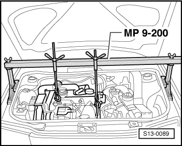
| 10 - | Engine support bracket |
| 11 - | Top toothed belt guard |
| 12 - | Timing belt |
| q | before removing mark running direction |
| q | check for wear |
| q | do not kink |
| q | removing and installing → Anchor |
| 13 - | Guide pulley |
| q | for vehicles 03.00 ? |
| 14 - | 20 Nm + torque a further (90°) 1/4 turn |
| q | replace |
| q | tightening to 90° may occur in successive stages |
| 15 - | 20 Nm |
| 16 - | screw for guide pulley |
| q | 17 Nm for console - → Item; spare part No. 038 903 143 E/F |
| q | 20 Nm for console - → Item; spare part No. 038 903 143 A/B |
| 17 - | 45 Nm |
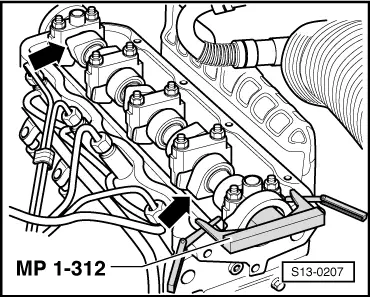
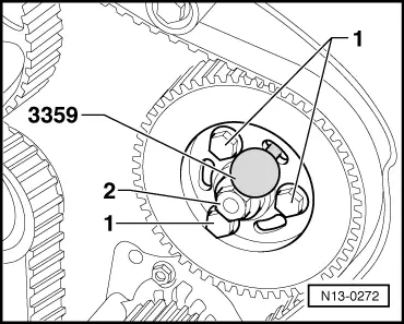
| q | hold camshaft sprocket with counterholder -MP 1-216 - for slackening and tightening |
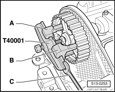
| 18 - | Camshaft sprocket |
| q | pull off from cone of camshaft with puller -T40001- |
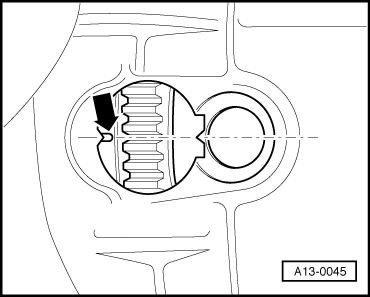
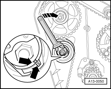
| 19 - | Semi-automatic tensioning pulley |
| q | inspecting semi-automatic timing belt tensioning pulley → Chapter |
| q | Fitting position → Fig. |
| 20 - | Guide pulley |
| 21 - | 30 Nm |
| 22 - | Rear timing belt guard |
| q | insert at the lower edge behind the front sealing flange |
| 23 - | Injection pump gear |
| q | for vehicles 08.97 ? |
| 24 - | Injection pump gear |
| q | for vehicles 07.97 ? |
| 25 - | Coolant pump |
| q | removing and installing → Chapter |
| 26 - | Guide pulley |
| q | to remove, unscrew the coolant pump |
| 27 - | Timing belt gear - crankshaft |
| q | there must not be any oil present on contact surface between timing belt sprocket and the crankshaft |
| q | Fitting position: the flats on the timing belt gear and the crankshaft must correspond |
| 28 - | Bush |
| 29 - | Nut |
| q | insert in bush → Item |
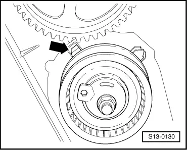
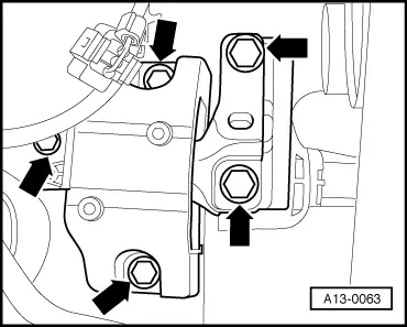
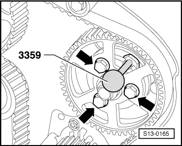
| 30 - | Injection pump |
| q | do not unscrew central nut -arrow- |
| q | removing and installing → 1.9 ltr./66 kW (TDI) Engine, Fuel Injection and Glow Plug System → Rep. Gr.23 |
| 31 - | 45 Nm |
| 32 - | Console |
| q | for vehicles without air conditioning |
| q | for injection pump, generator and vane pump |
|
|
 Note
Note
|
|
Note
Note
|
|
Note
|
|
|
|
Note
|
|
 WARNING
|
|
|
|
|
|