skoda Workshop Repair Guides

Skoda Workshop Service and Repair Manuals

Injection pump - summary of components > < Check intake manifold temperature sender G72
Check throttle valve positioner V60
Check throttle valve positioner -V60-
For vehicles 09.98 ? Intake manifold flap motor -V157-
Special tools and workshop equipment required
t  Vehicle system tester -V.A.G 1552- with cable -V.A.G 1551/3, 3A, 3B oder 3C-
t  Handheld multimeter (e.g. -V.A.G 1526A-)
t  Test box -V.A.G 1598/22- or -V.A.G 1598/31-
Test sequence
–  Connect vehicle system tester -V.A.G 1552- and select engine electronics control unit (address word 01). The engine must be idling for this step → Chapter.
   
Readout on display:
–  Enter 03 for the function “Actuator diagnosis”.
 
Vehicle system test               HELP
Select function XX
Readout on display:
–  Confirm entry with key Q.
 
Vehicle system test                  Q
03 - Actuator diagnosis
–  Press the button so often until in the display, appears:
Activating the throttle valve positioner generates differences in the combustion sound (the control motor opens and closes the intake manifold flap).
If no difference in sound can be heard:
–  Enter 06 for the function “End output” and confirm the entry with key Q.
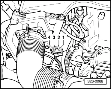
–  Switch off ignition.
 
Actuator diagnosis                        ->
Throttle valve positioner V60
–  Unplug the 4-pin connector from the intake manifold flap.
–  Switch on ignition.
–  Use handheld multimeter to measure voltage between the contacts 1 and 4 at the 4-pin plug.
Specified value: battery voltage
If the specified value is not reached:
–  Switch off ignition.
–  The following cable connections of contact 1 and 4 must be tested for short circuit to positive or negative and for interruption → Current flow diagrams and Fitting locations.
If the nominal value is measured:
–  Connect test box -V.A.G 1598/22- or -V.A.G 1598/31- at wiring loom to engine control unit → Chapter.
–  Test wiring (contacts 2 and 3) for short circuit to positive or negative and for open circuit according to current flow diagram → Current flow diagrams and Fitting locations.
–  If necessary eliminate wire interruption or short-circuit.
If the lines are not found to be faulty:
–  Replace throttle valve positioner -V60- → Chapter.
  S23-0068

Injection pump - summary of components > < Check intake manifold temperature sender G72