skoda Workshop Repair Guides

Skoda Workshop Service and Repair Manuals

Check engine speed sender G28 > < Test control unit input sizes
Check supply voltage for diesel direct injection system
The power supply of the injection system occurs via the diesel direct injection system relay -J322-.
The precondition for the closing of the relay -J322 - is a voltage supply via terminal 15 to the engine control unit.
Special tools and workshop equipment required
t  Handheld multimeter (e.g. -V.A.G 1526 A-)
t  Measuring tool set (e.g. -V.A.G 1594 A-)
t  Test box -V.A.G 1598/22- or -V.A.G 1598/31-
Check supply voltage terminal 15
Test conditions
l  Fuses No. 29 and 43 o.k.
l  Battery voltage O.K
Test sequence
–  Connect test box to wiring loom to engine control unit → Chapter.
For the test box -V.A.G 1598/22-
–  Connect multimeter for voltage measurement to bush 47 of test box and earth.
For the test box -V.A.G 1598/31-
–  Connect multimeter for voltage measurement to bush 37 of test box and earth.
For all vehicles
–  Switch on ignition.
Specified value: battery voltage
If the specified value is not reached:
–  Test wiring → Current flow diagrams and Fitting locations.
Test earth control of diesel direct injection system relay -J322-
Test conditions
l  Battery voltage O.K
l  Voltage supply on terminal 15 O.K
l  Fuses No. 29 and 43 o.k.
For the test box -1598/22-
For vehicles ? 07.97
–  Switch on ignition.
   
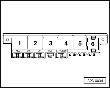
Specified value: Diesel direct injection system relay must be tightened (electrical centre, relay position 5).
  Note
The clicking of the relay is difficult to hear and can therefore best be felt.
If the specified value is not reached:
–  Connect test box to wiring loom to engine control unit → Chapter.
–  Interconnect bush 33 and bush 1 of the test box using an auxiliary line.
Specified value: Diesel direct injection system relay (electrical centre, relay position 5) must be tightened.
If the relay is now activated but did not connect during the final control diagnosis:
–  Replacing engine control unit -J248- → Chapter.
If the relay is not activated:
–  Switch off ignition.
  A23-0034
–  Pull diesel direct injection system relay -J322- from the relay base (electrical centre, relay position 5).
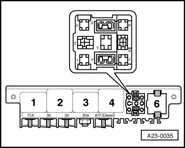
Test the following cable connections for short circuit to positive or negative and for interruption.
  A23-0035
Electrical centre, relay base 5, contactTest box -V.A.G 1598/22- bush
933

–  If necessary eliminate wire interruption or short-circuit → Current flow diagrams and Fitting locations.
For vehicles 08.97 ?
–  Switch on ignition.
   
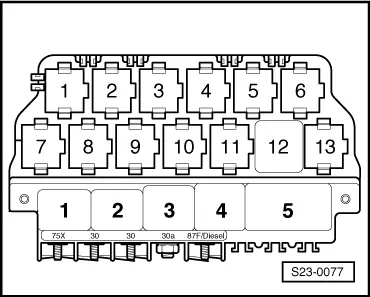
Specified value: Diesel direct injection system relay must be tightened (additional relay holder, relay position 12).
  Note
The clicking of the relay is difficult to hear and can therefore best be felt.
If the specified value is not reached:
–  Connect test box to wiring loom to engine control unit → Chapter.
–  Interconnect bush 33 and bush 1 of the test box using an auxiliary line.
Specified value: Diesel direct injection system relay (additional relay holder, relay position 12) must be tightened.
If the relay is now activated but did not connect during the final control diagnosis:
–  Replacing engine control unit -J248- → Chapter.
If the relay is not activated:
–  Switch off ignition.
  S23-0077
–  Pull diesel direct injection system relay -J322- from the relay base (additional relay holder, relay position 12).
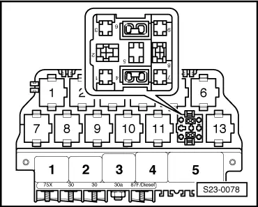
–  Test the following cable connections for short circuit to positive or negative and for interruption.
  S23-0078
Electrical centre, relay base 12, contactTest box -V.A.G 1598/22- bush
933

–  If necessary eliminate wire interruption or short-circuit → Current flow diagrams and Fitting locations.
For the test box -V.A.G 1598/31-
–  Switch on ignition.
   
Specified value: Diesel direct injection system relay must be tightened (additional relay holder, relay position 12).
  Note
The clicking of the relay is difficult to hear and can therefore best be felt.
If the specified value is not reached:
–  Connect test box at wiring loom to the engine control unit. The engine control unit is not connected → Chapter.
–  Interconnect bushes 18 + 4 of the test box using an auxiliary line.
Specified value: Diesel direct injection system relay (additional relay holder, relay position 12) must be tightened.
If the relay is now activated but did not connect during the final control diagnosis:
–  Replacing engine control unit -J248- → Chapter.
If the relay is not activated:
–  Switch off ignition.
  S23-0077
–  Pull diesel direct injection system relay -J322- from the relay base (additional relay holder, relay position 12).
–  Test the following cable connections for short circuit to positive or negative and for interruption.
  S23-0078
Electrical centre, relay base 12, contactTest box -V.A.G 1598/31- bush
918

–  If necessary eliminate wire interruption or short-circuit → Current flow diagrams and Fitting locations.
Check supply voltage terminal 30
Test conditions
l  Battery voltage O.K
l  Supply voltage terminal 15 O.K
l  Earth control of diesel direct injection system relay -J322- o.k.
l  Fuses No. 29 and 43 o.k.
Test sequence
–  Switch off ignition.
For the test box -1598/22-
For vehicles ? 07.97
   
–  Pull diesel direct injection system relay -J322- from the relay base (electrical centre, relay position 5).
–  Connect the multimeter for voltage measurement to the following contacts of the relay base.
  A23-0035
Electrical centre, relay base 5, contactSpecified value
2 + earthapprox. battery voltage

If the specified value is not reached:
–  Test the wiring, eliminate possible open circuits or short-circuits according to current flow diagram → Current flow diagrams and Fitting locations.
If the specified value is reached:
–  Fit relay again onto the relay base (electrical centre, relay position 5).
For vehicles 08.97 ?
   
–  Pull diesel direct injection system relay -J322- from the relay base (additional relay holder, relay position 12).
–  Connect the multimeter for voltage measurement to the following contacts of the relay base.
  S23-0078
Electrical centre, relay base 12, contactSpecified value
2 + earthapprox. battery voltage

If the specified value is not reached:
–  Test the wiring, eliminate possible open circuits or short-circuits according to current flow diagram → Current flow diagrams and Fitting locations.
If the specified value is reached:
–  Fit relay again onto the relay base (additional relay holder, relay position 12).
For all vehicles
–  Connect test box to wiring loom to engine control unit → Chapter.
–  Interconnect bush 33 and bush 1 of the test box using an auxiliary line.
–  Connect the multimeter for voltage measurement to the following contacts of the test box.
   
Test box -V.A.G 1598/22- bushSpecified value
2 + 1approx. battery voltage
28 + 1approx. battery voltage
2 + 27approx. battery voltage
28 + 27approx. battery voltage

If the specified value is not reached:
–  Test the wiring, eliminate possible open circuits or short-circuits according to current flow diagram → Current flow diagrams and Fitting locations.
For the test box -V.A.G 1598/31-
   
–  Pull diesel direct injection system relay -J322- from the relay base (additional relay holder, relay position 12).
–  Connect the multimeter for voltage measurement to the following contacts of the relay base.
  S23-0078
Electrical centre, relay base 12, contactSpecified value
2 + earthapprox. battery voltage

If the specified value is not reached:
–  Test the wiring, eliminate possible open circuits or short-circuits according to current flow diagram → Current flow diagrams and Fitting locations.
If the specified value is reached:
–  Fit relay again onto the relay base (additional relay holder, relay position 12).
–  Connect test box -V.A.G 1598/31 - at wiring loom to the engine control unit. The engine control unit is not connected → Chapter.
–  Interconnect bush 18 and bush 4 of the test box using an auxiliary line.
–  Connect the multimeter for voltage measurement to the following contacts of the test box.
   
Test box -V.A.G 1598/31- bushSpecified value
1 + 4approx. battery voltage
2 + 4approx. battery voltage
1 + 5approx. battery voltage
2 + 5approx. battery voltage

If the specified value is not reached:
–  Test the wiring, eliminate possible open circuits or short-circuits according to current flow diagram → Current flow diagrams and Fitting locations.
   

Check engine speed sender G28 > < Test control unit input sizes