
Octavia Mk1
|
|
|
|
|
|
|
| Test conditions | Display field 3 |
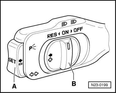
| Switch -B- to “ON” | 000011 |
| Switch -B- to “RES” | 001011 |
| Switch -A- operated | 000111 |
| Switch -B- to “OFF” before operating point | 000001 |
| Switch -B- locked to “OFF” | 000000 |
| Brake pedal actuated | 010011 |
| Clutch pedal actuated | 100011 |
|
|
|
| CCS switch | 10-pin plug on CCS switch, contact | Specified value |
| Switch -B- to “ON” | 4 + 5 6 + 7 | max. 1.5 Ω |
| Switch -B- to “RES” | 4 + 5 2 + 7 6 + 7 | max. 1.5 Ω |
| Switch -A- operated | 3 + 7 | max. 1.5 Ω |
| Switch -B- operated in “OFF” | 6 + 7 4 + 5 | max. 1.5 Ω ∞ Ω |
| Switch -B- locked to “OFF” | 6 + 7 2 + 7 4 + 5 | ∞ Ω |
|