
Octavia Mk1
|
| Reading measured value block | 0 | → | ← Read-out on display | ||||||||||
| 42 | 50 | 0 | 20 | 90 | 201 | 64 | 153 | 127 | 83 | ||||
Inducted air mass 1) 69...96 o.k.
| |||||||||||||
| Fuel temperature: 91...201 | |||||||||||||
| Intake manifold temperature: 182...50 | |||||||||||||
Coolant temperature: 80...35 o.k.
| |||||||||||||
| Ambient air pressure: ignore | |||||||||||||
| Charge pressure: ignore | |||||||||||||
Injection rate: 11...45 o.k.
| |||||||||||||
| Accelerator pedal position: 0 | |||||||||||||
Commencement of injection: 12...75 o.k.
| |||||||||||||
Idling speed: 42...45 o.k.
| |||||||||||||
|
| Reading measured value block | 0 | → | ← Read-out on display | ||||||||||
| 42 | 50 | 0 | 20 | 90 | 201 | 64 | 153 | 127 | 83 | ||||
Inducted air mass 1) 69...110 o.k.
| |||||||||||||
| Fuel temperature: 91...201 | |||||||||||||
| Intake manifold temperature: 190...80 | |||||||||||||
Coolant temperature: 80...35 o.k.
| |||||||||||||
| Ambient air pressure: ignore | |||||||||||||
| Charge pressure: ignore | |||||||||||||
Injection rate: 15...45 o.k.
| |||||||||||||
| Accelerator pedal position: 0 | |||||||||||||
Commencement of injection: 12...75 o.k.
| |||||||||||||
Idling speed: 43...46 o.k.
| |||||||||||||
| Read measured value block 1 → | ← Read-out on display | |||||||||||||||||||
| 900 rpm | 5.6 mg/s | 1.480 V | 87.3 °C | |||||||||||||||||
Coolant temperature
| ||||||||||||||||||||
Voltage of modulating piston movement sender -G149-
| ||||||||||||||||||||
Injection rate
| ||||||||||||||||||||
Engine speed
| ||||||||||||||||||||
|
| Read measured value block 1 → | ← Read-out on display | |||||||||||||||||||
| 900 rpm | 5.6 mg/s | 1.720 V | 87.3 °C | |||||||||||||||||
Coolant temperature
| ||||||||||||||||||||
Voltage of modulating piston movement sender -G149-
| ||||||||||||||||||||
Injection rate
| ||||||||||||||||||||
| Engine speed → Anchor | ||||||||||||||||||||
|
| Read measured value block 2 → | ← Read-out on display | |||||||||
| 900 rpm | 0.0 % | 0 1 0 | 88.4 °C | |||||||
Coolant temperature
| ||||||||||
| Operating position → Anchor | ||||||||||
Accelerator pedal position
| ||||||||||
| Engine speed → Anchor | ||||||||||
|
| Meaning, if display positions = 1 | |||||||||
| x | x | x | Engine operating condition | ||||||
| 1 | Signal of air conditioning system - switch off air conditioning system | ||||||||
| 1 | o.k.: (Idling switch closed) | ||||||||
| 1 | Idling speed increases:
| ||||||||
|
| Read measured value block 3 → | ← Read-out on display | |||||||||||||||||||||||||
| 900 rpm | 290 mg/s | 308 mg/s | 54 % | |||||||||||||||||||||||
On/off ratio (actuation) of exhaust gas recirculation valve
| ||||||||||||||||||||||||||
Drawn in air mass
| ||||||||||||||||||||||||||
The nominal air mass pumped by the control unit
| ||||||||||||||||||||||||||
| Engine speed → Anchor | ||||||||||||||||||||||||||
|
| Read measured value block 4 → | ← Read-out on display | |||||||||||||||||||||
| 900 rpm | 0.9° b.TDC | 0.9° b.TDC | 3 % | |||||||||||||||||||
On/off ratio (actuation) of commencement of injection valve
| ||||||||||||||||||||||
Momentary commencement of injection
| ||||||||||||||||||||||
The nominal injection commencement pumped by the control unit
| ||||||||||||||||||||||
| Engine speed → Anchor | ||||||||||||||||||||||
|
| Read measured value block 6 → | ← Read-out on display | |||||
| 0 km/h | 000 | 000000 | 0 | |||
| CCS Operating condition → Anchor | ||||||
| Operating condition of cruise control → Anchor | ||||||
| Brake pedal monitoring → Anchor | ||||||
| Speed: ignore | ||||||
|
| Display field 2 | Operating condition of the clutch pedal and brake pedal | X | X | X | Operating condition of the pedal switch at display positions = 1 |
| 000 | Clutch pedal and brake pedal not pressed | 1 | Brake light switch -F- closed | ||
| 011 | Brake pedal depressed (brake light switch) | ||||
| 011 | Brake pedal depressed (brake pedal switch) | 1 | Brake pedal switch -F47- open | ||
| 100 | Clutch pedal actuated | 1 | Clutch pedal switch -F36- open | ||
| 111 | Clutch pedal and brake pedal pressed |
|
|
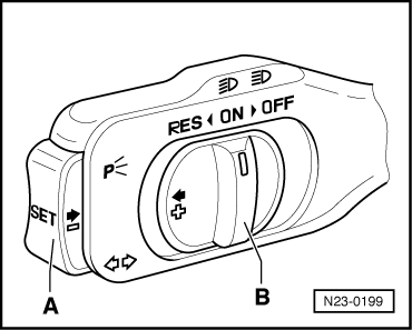
| Cruise control | Display field 3 |
| Switch -B- to “ON” | 000011 |
| Switch -B- to “RES” | 001011 |
| Switch -A- operated | 000111 |
| Switch -B- to “OFF” before operating point | 000001 |
| Switch -B- locked to “OFF” | 000000 |
| Brake pedal actuated | 010011 |
| Clutch pedal actuated | 100011 |
|
| CCS Operating condition | |
| 0 | Vehicle with CCS - CCS switched off |
| 1 | Vehicle with CCS - CCS switched on |
| 2 5 5 | Vehicle without CCS, or CCS function in engine control unit not activated |
|
 WARNING
| Read measured value block 7 → | ← Read-out on display | |||||||
| 15.4 °C | 15.9 °C | 16.7 °C | ||||||
Coolant temperature (at coolant temperature sender -G62-)
| ||||||||
Intake manifold temperature (at intake manifold temperature sender -G72-)
| ||||||||
| No display | ||||||||
Fuel temperature (at fuel temperature sender -G81-)
| ||||||||
 Note
Note
|
| Read measured value block 13 → | ← Read-out on display | |||||||||||
| 0.82 mg/s | -0.12 mg/s | 0.49 mg/s | -0.12 mg/s | |||||||||
Smooth running control - injected quantity cylinder 4
| ||||||||||||
Smooth running control - injected quantity cylinder 3
| ||||||||||||
Smooth running control - injected quantity cylinder 2
| ||||||||||||
Smooth running control - injected quantity cylinder 1
| ||||||||||||
|
| Read measured value block 16 → | ← Read-out on display | |||||
| 99.0 % | 10000001 | 00 | 14.2 V | |||
| Supply voltage from control unit: ignore | ||||||
| Heating element control → Anchor | ||||||
| Operating condition of the additional heating → Anchor | ||||||
| Generator capacity: ignore | ||||||
|
| Meaning, if display positions = 1 | ||||||||
| X | X | X | X | X | X | X | X | Additional heating deactivated, because: |
| 1 | Coolant temperature greater than 70...80°C or intake air temperature greater than 5°C 1) | |||||||
| 1 | AC generator defective | |||||||
| 1 | Battery voltage below 9 V | |||||||
| 1 | for vehicles ? 04.99 - engine speed below 875 rpm for vehicles 05.999 ? - engine speed below 861 rpm | |||||||
| 1 | Engine start within the last 10 seconds | |||||||
| 1 | Coolant temperature sender -G62- or intake manifold temperature sender -G72- defective | |||||||
| 1 | Ignore | |||||||
| 1 | Ignore | |||||||
|
| Meaning, if display positions = 1 | ||
| X | X | Heating element control |
| 1 | Low heat output relay -J359-, switched on | |
| 1 | High heat output relay -J360 -, switched on | |
|
| Read measured value block 19 → | ← Read-out on display | |||||||||||||
| 0.780 V | 4.150 V | |||||||||||||
| No display | ||||||||||||||
| No display | ||||||||||||||
Voltage of modulating piston movement sender at maximum limit of metering adjuster
| ||||||||||||||
Voltage of modulating piston movement sender at minimum limit of metering adjuster
| ||||||||||||||