skoda Workshop Repair Guides

Skoda Workshop Service and Repair Manuals

Replacing camshaft gasket ring > < Testing the compression
Repairing valve gear
  Note
t  Cylinder heads with cracks between the valve seats or between a valve seat ring and the spark plug thread may continue to be used without any reduction in life provided these are slight initial cracks which are not more than 0.3 mm wide, or cracks exist only at the first 4 turns of the spark plug thread.
t  
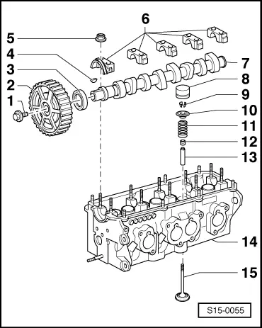
After installing new bucket tappets, the engine must not be started for about 30 minutes (otherwise place the valves on the pistons).
t  After carrying out work on the valve gear, carefully crank engine at least 2 revolutions to ensure that no valve touches the piston when the engine is started.
1 - 100 Nm
–  to release and tighten use the counterholder -T30004-
2 - Camshaft sprocket
–  with sensor rotor for the Hall sensor -G40-
–  to remove and install, remove toothed belt → Chapter fix installation position by woodruff key -pos. 4-
3 - Gasket ring
–  replace → Chapter
4 - Woodruff key
–  check for firm seating
5 - 20 Nm
6 - Bearing caps
–  Fitting position → Fig.
–  Mounting sequence → Chapter
–  Lightly coat head contact surface 1 with sealant - AMV 174 004 01 -
7 - Camshaft
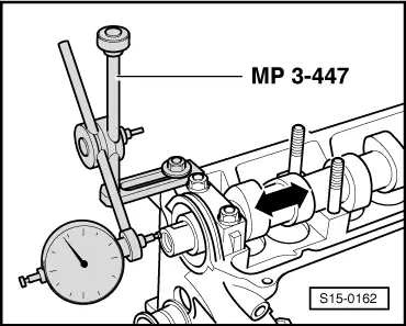
–  Inspecting axial play → Fig.
–  removing and installing → Chapter
–  Slack: max. 0.01 mm
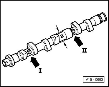
–  Identification, timing → Fig.
8 - Bucket tappets
–  do not interchange
–  with hydraulic valve clearance compensation
–  check → Chapter
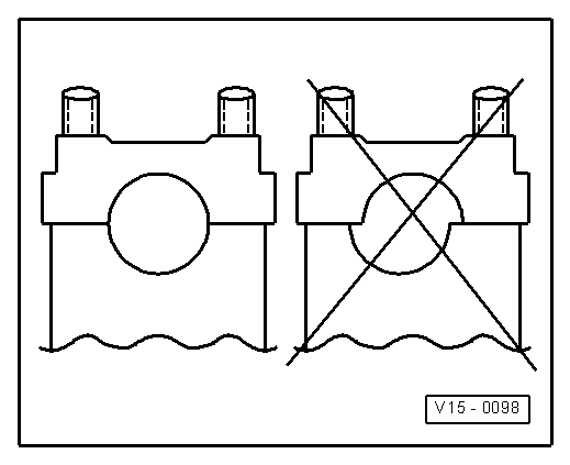
–  lay aside with contact surface facing down
–  before installing check axial play of the camshaft → Fig.
–  oil contact surface
9 - Collets
10 - Valve spring retainer
11 - Valve spring
–  removing and installing
–  with cylinder head removed: with -MP 1-211- and -MP 1-213- with valve supporting plate -MP 1-218 -
–  with cylinder head installed: → Chapter
12 - Valve stem seal
–  replace → Chapter
13 - Valve guide
–  check → Chapter
–  replace → Chapter
–  Repair of the guide with a collar
14 - Cylinder head
–  reworking valve seats → Chapter
15 - Valve
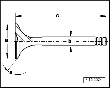
–  do not rework, only grinding in is permissible
–  Valve dimensions → Fig.
  S15-0055
inspect camshaft, axial play
Special tools and workshop equipment required
t  Universal dial gauge holder -MP 3-447-
t  Dial gauge
Wear limit: max. 0.15 mm
Perform measurement with the bucket tappets removed and the first and last bearing cap fitted.
  S15-0162
Fitting position of the camshaft bearing cap
Pay attention to centre displacement. Numbers on the bearing cap must be legible from the front.
  V15-0098
Valve dimensions
  Note
Valves must not be reworked. Only grinding in is permissible.
  V15-0024
DimensionInlet valveOutlet
valve
Ø amm39,5 ± 0,1532,9 ± 0,15
Ø bmm6,92 ± 0,026,92 ± 0,02
cmm91,8591,15
α∠°4545

   
Camshaft identification, timing
Identification
t  Base circle of cam: a = Ø 34 mm
t  Identification with digits and characters stamped in between the inlet and outlet cams:
  V15-0693
Cylinder 1 -arrow I-E or A
Cylinder 3 -arrow II-050


Replacing camshaft gasket ring > < Testing the compression