| Removing and installing, tightening the timing belt |

Note | Before removing the timing belt, mark direction of running. Reversing the rotation direction of an already used belt may destroy it. |
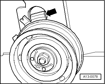
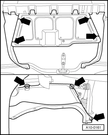
| 1 - | Timing belt guard - bottom part |
| –
| unscrew to remove the belt pulley/vibration damper → Chapter |
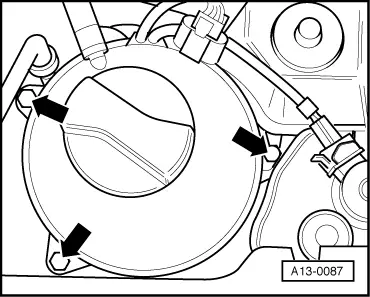
| 2 - | Timing belt guard - middle part |
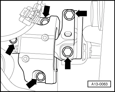
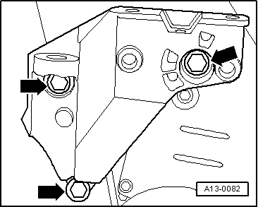
| 4 - | Engine support bracket |
| 6 - | Timing belt guard - top part |
| –
| before removing mark running direction |
| –
| to release and tighten the counterholder -T30004- and -MP 1-216- use |
| –
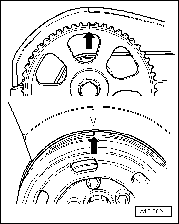
| with sensor rotor for camshaft position sensor -G40 - |
| –
| for removing and installing, remove toothed belt → Anchor |
| –
| Fix installation position by woodruff key pos. 14 |
| 15 - | Camshaft position sensor -G40- |
| –
| when bolting on, ensure base plate is centered |
| 17 - | Rear toothed belt guard |
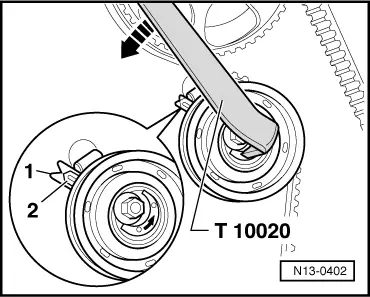
| 19 - | Toothed belt tensioning pulley |
| –
| check semi-automatic tensioning pulley → Chapter |
| 22 - | Toothed belt sprocket - crankshaft |
| –
| there must not be any oil present on the contact surface between the toothed belt sprocket and the crankshaft |
| –
| can be installed only in one position |
| 23 - | 90 Nm + torque a further 1/4 turn (90°) |
| –
| Fit bolt in original condition, do not oil or grease |
| –
| to release and tighten the counterholder -T30004- or -MP 1-310- use |
| –
| when bolting on counter-holder -MP 1-310-, place 2 washers between timing belt sprocket and counter-holder |
|
|

|