skoda Workshop Repair Guides

Skoda Workshop Service and Repair Manuals

Overview of radio system > < Radio system with 4 loudspeakers
Radio system with 8 loudspeakers
   
Bass speaker front right -3- and left -2-
t  installed in the door pocket
t  Diameter 168 mm
  S91-0010
Treble speaker front right -4- and left -1-
t  installed in the door at the top in the exterior mirror trim panel
t  Diameter 36 mm
Bass speaker rear right -7- and left -6-
t  in the support, installed on the right and left side
t  Diameter 130 mm
  S91-0010
Treble speaker rear right -8- and left -5-
t  installed next to the door handle
t  Diameter 36 mm
Contact assignment of multi-pin plug connections I, II and III on rear of radio - up to MY 98
  S91-0010
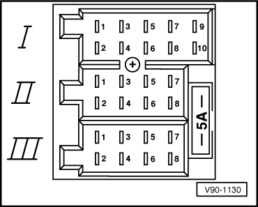
Multi-pin plug connection l, 10-pin
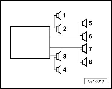
4 - Mute (telephone mode)
Multi-pin plug connection ll, 8-pin
1 - Speaker + rear right
2 - Speaker - rear right
3 - Speaker + front right
4 - Speaker - front right
5 - Speaker + front left
6 - Speaker - front left
7 - Speaker + rear left
8 - Speaker - rear left
Multi-pin plug connection lll, 8-pin
4 - Battery + (tml. 30)
5 - switched PLUS for electronically amplified roof aerial
6 - Lighting (tml. 58b)
7 - Connection for ignition key-controlled on and off (S-contact)
8 - Battery - (tml. 31)
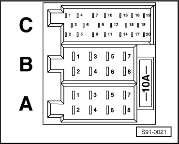
Contact assignment of multi-pin plug connections A, B, C on rear of radio - as of MY 99
Radio “Gamma”, Grundig MS 201, 401, 411, MS 303, “Symphony”
  V90-1130
Multi-pin plug connection A, 8-pin
1 - Function “gala” (volume adaptation - not valid for MS 201)
2 - Mute (telephone mode)
3 - Self-diagnosis/K wire
4 - Connection for ignition key-controlled on and off (S-contact)
5 - Battery + (terminal 30) - only for Gamma radio sets (for radio sets Grundig, MS 303 and Symphony not assigned)
6 - Lighting (tml. 58b)
7 - Battery + (tml. 30)
8 - Battery - (tml. 31)
Multi-pin plug connection B, 8-pin
1 - Speaker + rear right
2 - Speaker - rear right
3 - Speaker + front right
4 - Speaker - front right
5 - Speaker + front left
6 - Speaker - front left
7 - Speaker + rear left
8 - Speaker - rear left
Multi-pin plug connection C, part 1 (yellow)
1 - Line Out left rear; LR
2 - Line Out right rear; RR
3 - Line Out, earth
4 - Line Out left front; LF
5 - Line Out right front; RF
6 - Switched PLUS for sound amplifier
  S91-0021
Multi-pin plug connection C, part 2 (green)
7 - Telephone input signal; TEL+ (not for MS 201)
8 - Second display; CLOCK (not assigned for Grundig radio sets and radio sets with CAN databus communication)
9 - Second display; DATA (not assigned for Grundig radio sets and radio sets with CAN databus communication)
10 - Second display; ENA (not assigned for Grundig radio sets and radio sets with CAN databus communication)
11 - Remote control; REM (not assigned for Grundig radio sets)
12 - Telephone input signal; TEL - (not for MS 201)
Multi-pin plug connection C, part 3 (blue)
13 - CD changer; DATA IN (for Grundig radio sets DATA)
14 - CD changer; DATA OUT (for Grundig radio sets DATA)
15 - CD changer; CLOCK (for Grundig radio sets earth)
16 - CD changer; voltage supply (+), terminal 30
17 - CD changer; control signal
18 - CD changer; left and right channel, earth
19 - CD changer; left channel, CD/L
20 - CD changer; right channel, CD/R
  S91-0021

Overview of radio system > < Radio system with 4 loudspeakers