skoda Workshop Repair Guides

Skoda Workshop Service and Repair Manuals

Interrogating fault memory > < Removing and installing bracket for "TAXI” roof sign
Self diagnosis for the Xenon headlights with automatic regulation (System Litronic 4.1)
General Instructions
The system contains a discharge lamp D2S with automatic regulation of the headlight height depending on the angle of declination of the vehicle relative to the road surface.
The regulation of the headlight height works on the basis of data from two senders which are positioned on the front and rear axle. All of the evaluation values for adjusting the stepper motors are carried out in the left headlight (master) and after the connection of the electrical installation, the information is transferred to the right headlight (slave).
If faults arise in the Litronic system 4.1 (discharge failure, ignition unit does not work, line interruption of senders, front and rear sender defective) these faults are displayed by an orange warning light with the symbol of a lit light bulb in the dash panel insert. (only for L&K version).
Special tools and workshop equipment required
t  
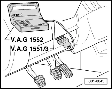
Vehicle system tester -V.A.G 1552- with cable -V.A.G 1551/3, 3A, 3B oder 3C-
Connecting vehicle system tester -V.A.G 1552-
Test conditions
l  Battery voltage at least 11.5 volts
l  Earth connection to engine and gearbox O.K.
l  Fuses must be OK in compliance with the current flow diagram.
The diagnostic connection is located in the storage compartment on the driver's side.
   
–  Connect vehicle system tester -V.A.G 1552- with appropriate cable.
–  Switch on ignition.
  S01-0045
Readout on display:
  Note
If there is no readout on the display: → Operating instructions of vehicle system tester.
Communication build-up is possible after entering the address word - 29 for master (left light), 39 for slave (right light).
–  Enter address word 29 or 39 "Xenon headlights" and confirm the entry with the key Q.
 
Vehicle system test               HELP
Select function XX
After approx. 5 secs the display will show e.g.:
t  1U0 941 651: Part no. of the control unit
t  ECG GDL + auto HRC: Designation
t  0001: Software version
t  Coding 00005: Coding
t  00123: Workshop code
  Note
Check coding with the table of codes → Chapter.
–  -> Press key.
 
1U041651 ECG GDL + auto HRC 0001      ->
Coding 00005                 WSC 00123
If one of the following messages appears on the display, carry out “fault finding” as specified in the fault finding programme in the diagnostic cable → Current flow diagrams and Fitting locations.
 
Vehicle system test               HELP
The control unit does not respond!
 
Vehicle system test               HELP
Fault in communication set-up
 
Vehicle system test               HELP
K cable does not connect to earth
–  After pressing the HELP button an overview of the possible functions is displayed.
–  Move forward in the programme with the -> key.
Overview of selectable functions
The following functions are possible.
02 - Interrogating fault memory → Chapter
03 - Actuator diagnosis → Chapter
04 - Initiate basic setting → Chapter
05 - Erasing fault memory → Chapter
06 - Ending output → Chapter
07 - Coding control unit → Chapter
08 - Reading measured value block → Chapter
 
Vehicle system test               HELP
K cable does not connect to pos. term.

Interrogating fault memory > < Removing and installing bracket for "TAXI” roof sign