
Octavia Mk1
| Summary of components - removing and installing gearbox housing and shift mechanism |
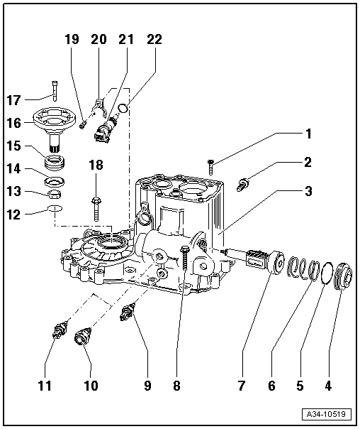
| 1 - | Oval-head countersunk screw, 15 Nm |
| q | M7 x 23 |
| q | 4 pieces |
| q | for tensioning plate/grooved ball bearing to gearbox housing |
| 2 - | 20 Nm |
| q | for shaft/reverse gear |
| 3 - | Gearbox housing |
| q | repairing → Chapter |
| q | as of gearbox manufacturing date 03 08 8 with additional threaded bore for the reversing light switch -F4 - Pos. 9 |
| q | Assembly of a gearbox housing with an additional threaded bore on gearboxes up to gearbox manufacturing date 02 08 8 → Fig. |
| 4 - | Screw cap, 50 Nm |
| 5 - | O-ring |
| q | always replace → Electronic Catalogue of Original Parts |
| 6 - | Pressure spring |
| q | presses gearshift shaft and shift lever into the 3rd and 4th gear gate |
| 7 - | Gearshift shaft |
| q | disassembling and assembling → Chapter |
| 8 - | 25 Nm |
| q | M8 x 35 |
| q | 2 pieces |
| q | screw in below the locking screw Pos. 11 or Pos. 10 |
| 9 - | Reversing light switch -F4-, 23 Nm |
| q | installed as of gearbox manufacturing date 03 08 8 |
| q | coat with sealant -AMV 188 200 03- |
| 10 - | Locking screw, 40 Nm |
| q | for gearshift shaft |
| q | installed as of gearbox manufacturing date 03 08 8 |
| q | coat with sealant -AMV 188 200 03- |
| 11 - | Reversing light switch -F4- and locking screw for gearshift shaft, 23 Nm |
| q | installed up to gearbox manufacturing date 02 08 8 |
| q | as of gearbox manufacturing date 03 08 8, the reversing light switch -F4- Pos. 9 and the locking screw Pos. 10 are two components → Fig. |
| q | coat with sealant -AMV 188 200 03- |
| 12 - | Circlip |
| q | holds the conical ring, stop disc and pressure spring in position when the flange shaft is removed |
| 13 - | Conical ring |
| q | with slots for thrust washer catch |
| q | Fitting position: Cone towards differential gear housing |
| 14 - | Thrust washer |
| q | Fitting position: Collar to pressure spring, leg (if present) to conical ring |
| 15 - | Pressure spring |
| 16 - | Flange shaft left |
| q | removing and installing → Chapter |
| 17 - | Conical screw, 25 Nm |
| 18 - | 25 Nm |
| q | M8 x 52 |
| q | 12 pieces |
| 19 - | 5 Nm |
| q | Fixing screw for speedometer drive Pos. 21 |
| 20 - | Support |
| 21 - | Drive for speedometer |
| 22 - | O-ring |
| q | always replace → Electronic Catalogue of Original Parts |
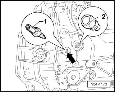
| Reversing light switch -F4--1- | 23 Nm |
| Locking screw -2- | 40 Nm |
|
|
|
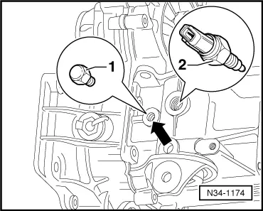
| Reversing light switch -F4--2- | 23 Nm |
| Hexagon screw M12 x 1.5 -1- | 25 Nm |