skoda Workshop Repair Guides

Skoda Workshop Service and Repair Manuals

Disassembling and assembling the shift rods with the shift forks > < Repairing the gearbox housing
Repairing the clutch housing
Special tools and workshop equipment required
t  Gearbox mount -MP3-501-
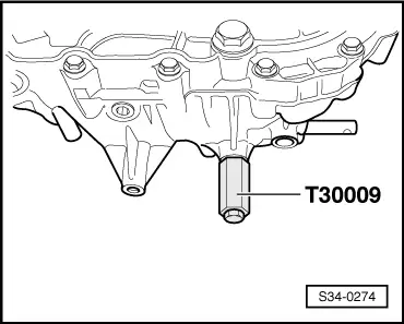
t  Wrench for threaded bush -T30009-
t  Multi-purpose tool -MP3-419 (VW771)-
t  Bushing -MP3-424 (30-21)-
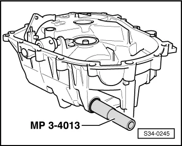
t  Pipe section -MP3-4013 (VW421)-
t  Extractor for locking pin -MP3-508- 4 mm
t  Attachment for inertia extractor -MP3-604 -
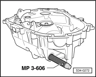
t  Retainer for bushings of gearshift shaft -MP3-606 -
t  Inertia extractor -MP9-501-
t  Sealant -THREE BOND 1305-
t  Sealant -THREE BOND 1324-
t  Locking agent -Loctite 648-
   
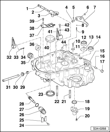
1 - Screw plug, 30 Nm
q   before installing apply sealant -THREE BOND 1324-
2 - Angle lever bolt
q   removing and installing → Fig.
3 - Elbow lever
4 - Bolt
q   for reverse gear lever
5 - Tensioning sleeve
q   4 x 25 mm
q   Install with extractor for locking pin -MP3-508- Ø 4 mm
6 - Plug
q   before installing apply sealant -THREE BOND 1305-
7 - Reverse gear lever
8 - Locking ball
9 - Catch spring
10 - Screw, 10 Nm
11 - Washer
12 - Cylindrical-roller bearing
q   for output shaft
q   removing and installing → Chapter Pos. 32
q   Fitting position → Fig.
13 - Supports
14 - Cylindrical-roller bearing
q   for drive shaft
q   removing and installing → Chapter Pos. 9
q   Fitting position → Fig.
15 - Clutch housing
16 - Ventilation tube
q   remove with pliers
q   drive in up to the stop with the drift
17 - Cap
q   for gearbox bleeder
18 - Gasket ring for drive shaft
q   removing → Fig.
q   installing → Fig.
19 - Guide bushing for clutch release bearing
20 - Screw, 10 Nm
q   before installing apply sealant -THREE BOND 1324-
21 - Pin screw, M10
22 - Pin screw, M10
23 - O-ring
q   for right flange shaft
q   replace → Chapter
24 - Screw, 20 Nm
25 - Support
26 - Guide bush
27 - O-ring
q   always replace
28 - Drive shaft with pinion
q   for speedometer
29 - Bushing
q   for gearshift shaft
q   removing → Fig.
q   inserting → Fig.
30 - Sealing ring
q   for gearshift shaft
q   can be replaced on an installed gearbox
q   release with a screwdriver
q   inserting → Fig.
31 - Gearshift shaft
32 - Sliding block arm
q   for removal, drive out the tensioning sleeves -33- and -34- downwards
q   for installing, drive in the tensioning sleeves from above
33 - Tensioning sleeve
q   Fitting position → Fig.
34 - Tensioning sleeve
q   Fitting position → Fig.
35 - Threaded bush, 50 Nm
q   before installing apply sealant -THREE BOND 1305-
q   removing and installing → Fig.
36 - Magnet
q   is held in position by the separator surface of the housing
37 - Sliding-block guide
38 - Lock washer
39 - Screw, 10 Nm
40 - Outer ring/tapered-roller bearing
q   for the differential gear
q   extracting and inserting → Chapter
q   when replacing: adjust the differential gear → Chapter
41 - Shift lever
q   Set the position of the shift lever → Fig.
42 - Screw, 15 Nm
q   apply locking agent -Loctite 648- before installing
43 - Lock washer
44 - Bushing for gear shift rod
q   removing → Fig.
q   inserting → Fig.

   
Remove and install angle lever bolt
Removing
–  Unscrew screw plug -1-.
–  Drive out angle lever bolt -2- with inertia extractor -MP9-501- and attachment for inertia extractor -MP3-604-.
Install
–  Install angle lever bolt -2-.
–  Coat screw plug -1- with sealant -THREE BOND 1324- and tighten to 30 Nm.
  S34-0021
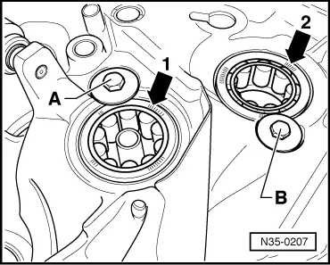
Fitting position of the cylindrical-roller bearing for input and output shaft
The marking on the cylindrical-roller bearings for the output shaft -arrow 1- and input shaft -arrow 2- must be visible after installation (pointing upwards).
After installation secure both bearings with screws -A- and -B-.
  N35-0207
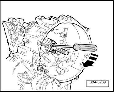
Removing gasket ring for drive shaft
  S34-0269
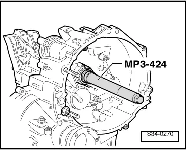
Drive on the gasket ring for drive shaft, not up to the stop
The correct fitting position of the gasket ring is obtained after fitting the guide bushing.
  S34-0270
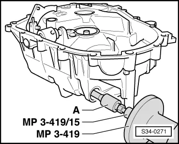
Remove bushing for gearshift shaft
-A- Interior extractor 14...19 mm, e.g. interior extractor -Kukko 21/2-
  S34-0271
Drive in the bushing for the gearshift shaft up to the stop
Secure the bushing at the same time against wandering with the striker -MP3-606-.
  S34-0272
Drive in the gasket ring up to the stop
  S34-0245
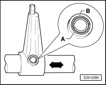
Fitting position of the tensioning sleeves for the sliding block arms
Both tensioning sleeves -A- and -B- are inserted into each other. Both slots must be positioned opposite each other and longitudinally to power flow -arrow-.
  S34-0286
Remove and install the threaded bush in the clutch housing
Removing
–  Screw threaded bush with wrench for threaded bush -T30009 - into the clutch housing.
–  Release threaded bush.
Install
–  Screw threaded bush with wrench for threaded bush -T30009-.
–  Coat the outside thread of the threaded bush with sealant -THREE BOND 1305-.
–  Screw the threaded bush into the clutch housing and tighten to tightening torque.
  S34-0274
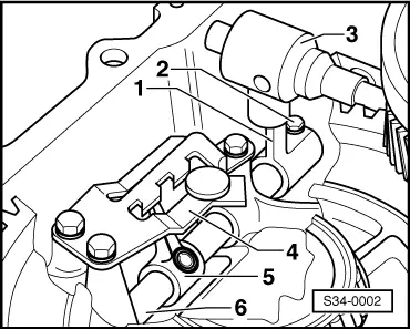
Set the position of the shift lever
  Note
t  The opening for securing the shift shaft -6- must point upwards.
t  When installing, the position of the shift lever -1- to the shift shaft -6- is important so that the end of the sliding block arm -5- does not come in contact with the sliding block guide -4- when the shift rod moves.
–  Screw in screw -2- with locking agent -Loctite 648-, do not tighten.
–  Adjust the end of the sliding block arm -5- in such a way that the sliding block arm -5- does not come in contact with the sliding block guide -4- when the shift rod moves.
–  Tighten screw -2- to 15 Nm.
–  The sliding block arm -5- must be replaced if the hole for the tensioning sleeves is damaged → Electronic Catalogue of Original Parts.
  S34-0002
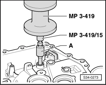
Remove bushing for gear shift rod
-A- Interior extractor 14...19 mm, e.g. interior extractor -Kukko 21/2-
  S34-0273
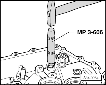
Drive in the bushing for the shiftrod up to the stop.
Secure the bushing at the same time against wandering with the striker -MP3-606-.
  S34-0064

Disassembling and assembling the shift rods with the shift forks > < Repairing the gearbox housing