
Octavia Mk1
|
|
|
|
|
|
|
|
 Note
Note
|
|
|
|
|
|
|
|
Note
Note |
|
|
|
|
|
|
|
Note
|
|
| Tightening torques |
| Component | Nm | |
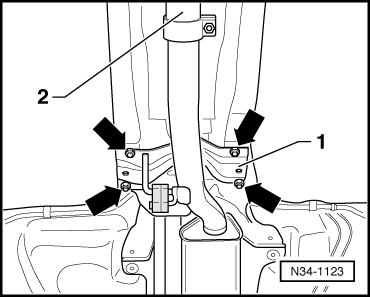
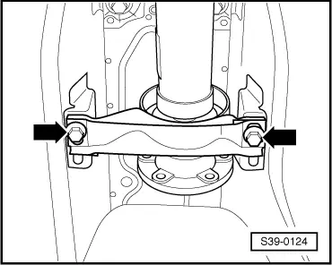
| Intermediate bearing to body | 25 | |
| Front to rear propshaft pipe | 40 | |
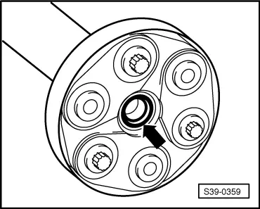
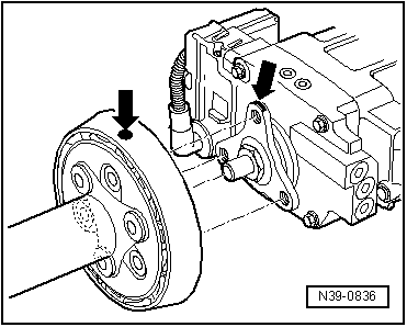
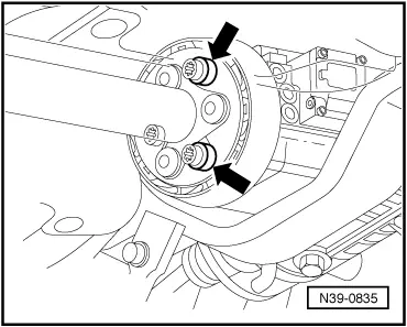
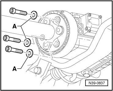
| Flexible disk to propshaft | 60 | |
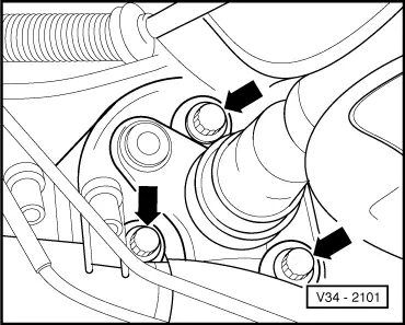
| Flexible disk to rear final drive | 60 | |
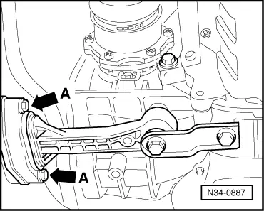
| Flexible disk to angle gearbox | 60 | |