skoda Workshop Repair Guides

Skoda Workshop Service and Repair Manuals

Adjusting washer table > < Disassembling and assembling the drive shaft up to gearbox manufacturing date 18 05 3
Setting drive shaft up to gearbox manufacturing date 18 05 3
  Note
t  The setting instruction is only valid for gearboxes up to gearbox manufacturing date 18 05 3 (bearing of drive shaft with tapered-roller bearings).
t  The bearing of the drive shaft is modified as of gearbox manufacturing date 19 05 3 → Chapter. Then the setting does not apply.
Special tools and workshop equipment required
t  Gauge block plate -MP3-405/17 (VW 385/17)-
t  Pressure spindle -MP3-423 (VW 407)-
t  Universal dial gauge holder -MP3-447 (VW 387)-
t  Gearbox mount -MP3-501- or gearbox mount -T30109 (VW 353)- with retaining plate -T30108-
t  Washer -MP6-415 (3260)-
t  Retaining plate -T30027 (VW 801)-
t  Thrust piece -T30042 (2050)-
t  Interior extractor 46...58 mm, e.g. -Kukko 21/7-
t  Countersupport e.g. -Kukko 22/2-
t  Dial gauge
The drive shaft must be re-set when the following components are replaced:
t  Gearbox housing
t  Clutch housing
t  Drive shaft
or
t  Tapered-roller bearing
Setting overview → Chapter.
l  Measured washer thicknesses for both output shafts are installed.
   
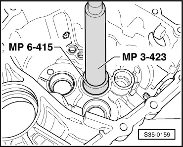
–  Press the outer ring/tapered-roller bearing up to the stop without adjusting washer into the gearbox housing. While doing so support the gearbox housing with a pressure plate -T30042 (2050)- directly below the bearing support.
–  Insert both output shafts and the drive shaft in the clutch housing and install gearbox housing. Tighten screws to 25 Nm.
  S35-0159
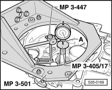
–  Fit measuring device and dial gauge in the clutch housing.
A - Dial gauge extension = 30 mm
–  Turn the drive shaft before measuring to ensure the tapered-roller bearing sets. Set the dial gauge to “0” with 1 mm bias.
  Note
This procedure must be repeated before each subsequent measurement, because otherwise the dial gauge does not return to its initial setting .
–  Pull drive shaft in direction of dial gauge.
–  Read off play on dial gauge and note (in the example = 1.63 mm).
–  Determine the thickness of the adjusting washer according to the table → Chapter (example 1.55 mm); part number → Electronic Catalogue of Original Parts.
  S35-0169
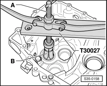
–  Remove the gearbox housing and pull out the outer ring/tapered-roller bearing from the gearbox housing.
A - Countersupport, e.g. -Kukko 22/2-
B - Interior extractor 46...58 mm, e.g. -Kukko 21/7-
  S35-0158
–  Insert the determined adjusting washer (in this example: 1.55 mm) and press the outer ring/tapered-roller bearing into the gearbox housing. While doing so, support the gearbox housing with a thrust piece -T30042 (2050)- directly below the bearing support.
–  Fit gearbox housing and tighten new screws to tightening torque → Chapter or → Chapter.
  S35-0159

Adjusting washer table > < Disassembling and assembling the drive shaft up to gearbox manufacturing date 18 05 3