
Octavia Mk1
 Note
Note| t | When installing new pinions or a new output shaft observe the technical data → Chapter. |
| t | If the output shaft or tapered-roller bearing is replaced, it is necessary to adjust the output shaft → Chapter. |
| t | Both tapered-roller bearings are replaced together. |
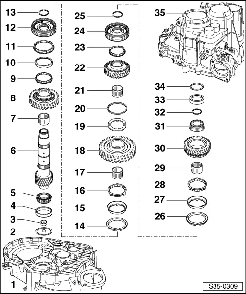
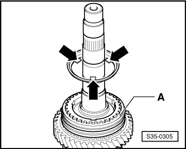
| 1 - | Clutch housing |
| 2 - | Oil deflecting washer |
| 3 - | Curved washer |
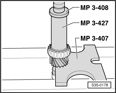
| q | removing → Fig. |
| q | installing → Fig. |
| q | replace after disassembly → Electronic Catalogue of Original Parts |
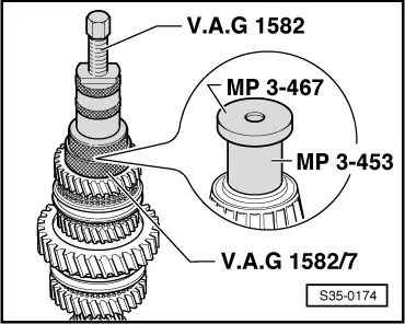
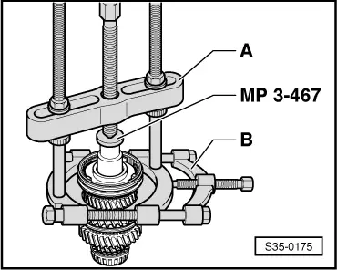
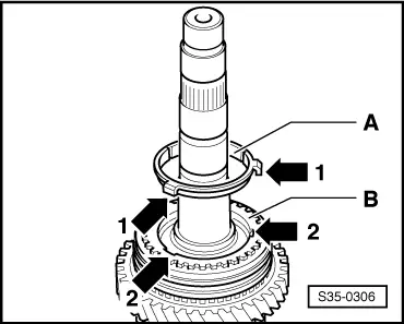
| 4 - | Outer ring/tapered-roller bearing |
| q | removing → Fig. |
| q | installing → Fig. |
| 5 - | Inner ring/tapered-roller bearing |
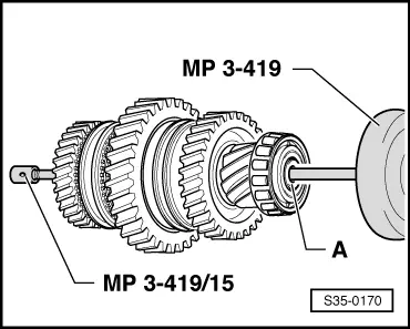
| q | pressing off → Fig. |
| q | pressing on → Fig. |
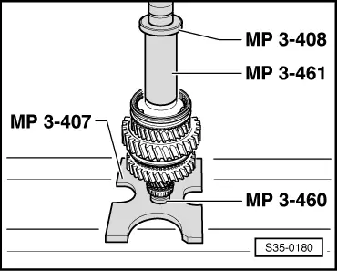
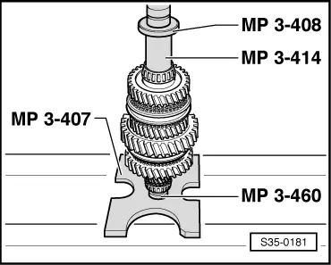
| 6 - | Output shaft |
| q | 1st to 4th gear |
| q | adjust → Chapter |
| 7 - | Needle bearing |
| q | for 2nd gear |
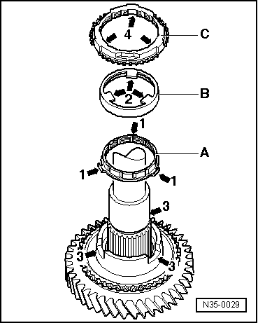
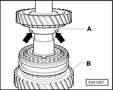
| 8 - | 2nd gear sliding gear |
| 9 - | Synchronizer ring |
| q | (Inner ring for 2nd gear) |
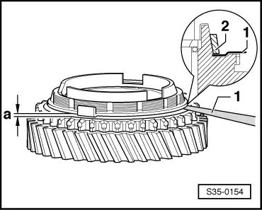
| q | check for wear → Fig. |
| q | Check pegs for traces of wear |
| q | Fitting position → Fig. |
| 10 - | Outer ring for 2nd gear |
| q | position on the synchronizer ring -Pos. 9- |
| q | replace if there are any traces of scoring or friction |
| q | Fitting position → Fig. |
| 11 - | 2nd gear synchronizer ring |
| q | check for wear → Fig. |
| q | Fitting position → Fig. |
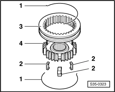
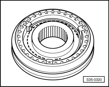
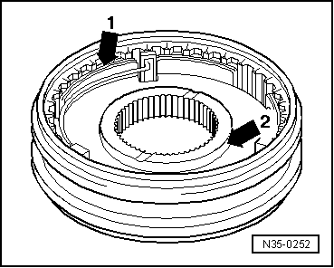
| 12 - | Sliding sleeve with 1st and 2nd gear synchronizer body |
| q | after removing the circlip -Pos. 13- press off with the 2nd gear sliding gear → Fig. |
| q | disassembling → Fig. |
| q | Assembling sliding sleeve/synchronizer body → Fig. and → Fig. |
| q | Fitting position → Fig. |
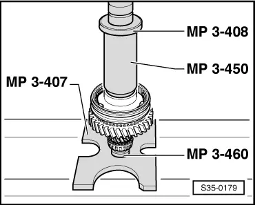
| q | pressing on → Fig. |
| 13 - | Circlip |
| 14 - | 1st gear synchronizer ring |
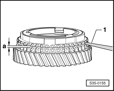
| q | check for wear → Fig. |
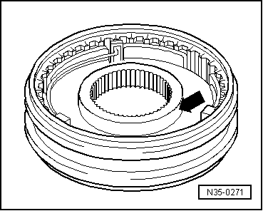
| q | insert in such a way that the recesses lock into the arresters of the sliding sleeve/synchronizer body Pos. 12 |
| 15 - | Outer ring for 1st gear |
| q | insert into synchronizer ring Pos. 14, fitting position → Fig. |
| q | replace if there are any traces of scoring or friction |
| 16 - | Synchronizer ring |
| q | (Inner ring for 1st gear) |
| q | check for wear → Fig. |
| q | Check pegs for traces of wear |
| q | Fitting position → Fig. |
| 17 - | Needle bearing |
| q | for 1st gear |
| 18 - | 1st gear sliding gear |
| q | Fitting position → Fig. |
| 19 - | Thrust washers |
| q | for 1st and 4th gear |
| q | 2 pieces |
| q | Insert peg of thrust washer into the hole of the output shaft |
| 20 - | Washer |
| q | holds the thrust washers pos. 19 in the correct position on the output shaft |
| 21 - | Needle bearing |
| q | for 4th gear |
| 22 - | 4th gear sliding gear |
| 23 - | 4th gear synchronizer ring |
| q | check for wear → Fig. |
| 24 - | Sliding sleeve with 3rd and 4th gear synchronizer body |
| q | after removing the circlip -Pos. 25- remove with the 4th gear sliding gear → Fig. |
| q | disassembling → Fig. |
| q | Fitting position sliding sleeve/synchronizer body → Fig. |
| q | Assembling sliding sleeve/synchronizer body → Fig. and → Fig. |
| q | pressing on → Fig. |
| 25 - | Circlip |
| 26 - | 3rd gear synchronizer ring |
| q | check for wear → Fig. |
| 27 - | Outer ring for 3rd gear |
| q | fit into synchronizer ring -Pos. 26-, fitting position → Fig. |
| q | replace if there are any traces of scoring or friction |
| 28 - | Synchronizer ring |
| q | (Inner ring for 3rd gear) |
| q | check for wear → Fig. |
| q | Check pegs for traces of wear |
| q | Fitting position → Fig. |
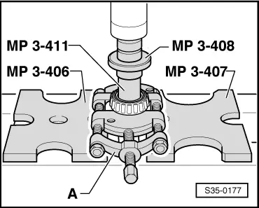
| 29 - | Needle bearing |
| q | for 3rd gear |
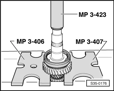
| 30 - | 3rd gear sliding gear |
| q | Fitting position → Fig. |
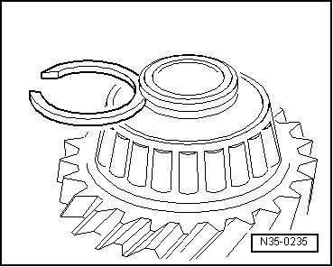
| 31 - | Inner ring/tapered-roller bearing |
| q | remove → Fig. |
| q | pressing on → Fig. |
| 32 - | Circlip |
| q | determine the thickness again when replacing the tapered-roller bearing Pos. 31 and the output shaft Pos. 6 → Fig. |
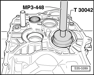
| 33 - | Outer ring/tapered-roller bearing |
| q | removing → Fig. |
| q | installing → Fig. |
| 34 - | Adjusting washer |
| q | Determine thickness → Chapter |
| 35 - | Gearbox housing |
|
|
Note
|
|
|

|
|
|
|
|
|
|
|
|
|
|
|
|
|
|
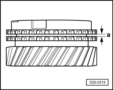
| Clearance -a- | Fitting dimension | Wear limit |
| 1st, 2nd and 3rd gear | 0.75…1.25 mm | 0.3 mm |
|
|
| Clearance -a- | Fitting dimension | Wear limit |
| 1st, 2nd and 3rd gear | 1.2…1.8 mm | 0.5 mm |
|
|
|
|
|
|
|
|
|
|
|
|
|
|
|
|
|
|
|
|
|
|
| Clearance -a- | Fitting dimension | Wear limit |
| 4th gear | 1.0…1.7 mm | 0.5 mm |
|
|
|
|
| Thickness (mm) | ||
| 1,79 | 1,89 | 1,98 |
| 1,83 | 1,92 | |
| 1,86 | 1,95 | |
|
|
|
|
|