
Octavia Mk1
| Summary of components - engines with identification characters AVU, BFQ |
 Note
Note| For carrying out removal and installation operation, attach the engine with the engine holder -MP1-202- and the sleeves -T30010- to the assembly stand -MP9-101-. |

| 1 - | Circlip |
| 2 - | Piston pin |
| q | if stiff, heat piston to 60°C |
| q | use drift -VW 222 A- for removing and installing |
| 3 - | Piston |
| q | check → Fig. |
| q | mark installation position relative to conrod and mark matching cylinder with felt pen |
| q | arrow on the piston crown faces towards the belt pulley side |
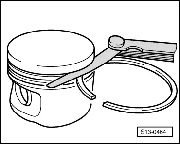
| q | use piston ring tensioning strap for installing |
| q | Ø Piston 80.965 mm - without graphite coating 0.02 mm |
| 4 - | Piston ring (compression ring) |
| q | Offset joint 120° |
| q | use piston ring pliers for removing and installing compression rings |
| q | marking „TOP“ must face towards piston crown |
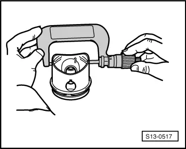
| q | Inspect gap clearance → Fig. |
| q | Inspect end clearance → Fig. |
| 5 - | Piston ring (oil scraper ring) |
| q | carefully remove and install by hand |
| q | marking „TOP“ must face towards piston crown |
| q | Inspect gap clearance → Fig. |
| q | Inspect end clearance → Fig. |
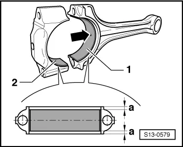
| 6 - | Conrod |
| q | replace as a set only |
| q | separate new conrod → Chapter |
| q | mark assignment to cylinder -B- |
| q | Fitting position: |
| Markings -A- must be positioned one above the other and point to the belt pulley side |
| q | with oil drilling for lubricating piston pin |
| 7 - | Conrod bearing cap |
| q | as a result of the conrods separated in the cracking process, the cover fits only in one position and only to the relevant conrod |
| q | mark assignment to cylinder -B- |
| q | Fitting position: |
| Markings -A- must be positioned one above the other and point to the belt pulley side |
| 8 - | 30 Nm + torque a further 90° (1/4 turn) |
| q | replace |
| q | Oil thread and contact surface |
| 9 - | Pressure relief valve, 27 Nm |
| q | opens at: |
| 0.13…0.16 MPa (1.3…1.6 bar) |
| q | replace without sealant |
| 10 - | Oil injection nozzle |
| q | for piston cooling |
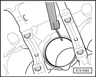
| 11 - | Cylinder block |
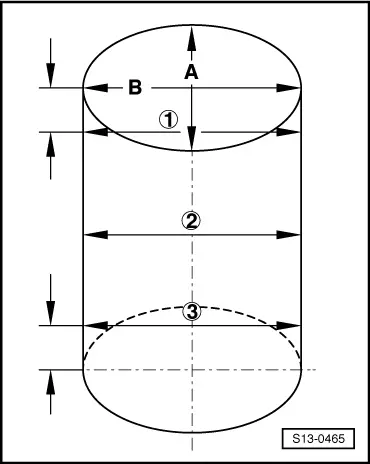
| q | inspect cylinder bore → Fig. |
| q | Ø Cylinder 81.01 mm |
| 12 - | Bearing shell |
| q | check fitting position → Fig. |
| q | do not mix up used bearing shells |
| q | insert bearing shells in the centre |
| q | Axial play when new: 0,05…0,31 mm |
| Wear limit: 0,37 mm |
| q | with oil drilling -arrow- for lubricating piston pin |
| Piston ring | Gap clearance | |
| new (mm) | Wear limit (mm) | |
| Compression rings | 0,75…1,00 | 1,3…1,4 |
| Oil scraper ring | 0,25…0,50 | 0,80 |
|
|
| Piston ring | End clearance | |
| new (mm) | Wear limit (mm) | |
| Compression rings | 0,06…0,09 | 0,20 |
| Oil scraper ring | 0,03…0,06 | 0,15 |
|
|
|
|
Note
|
|