
Octavia Mk1
| Overview of fitting locations - engines with identification characters AVU, BFQ |
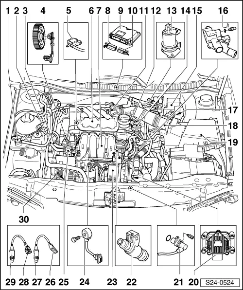
| 1 - | Solenoid valve 1 for activated charcoal filter -N80- |
| q | Resistance value: 22…30 Ω |
| 2 - | Return-flow line |
| q | secure with spring strap clamps |
| q | to the fuel delivery unit in the fuel tank |
| 3 - | Feed line |
| q | secure with spring strap clamps |
| q | from fuel filter |
| 4 - | Camshaft position sensor -G163- |
| q | for engines with identification characters AVU |
| q | under top toothed belt guard |
| 5 - | Valve for variable intake manifold changeover -N156- |
| 6 - | Top part of intake manifold |
| q | disassembling and assembling → Chapter |
| 7 - | Bottom part of intake manifold |
| 8 - | 81-pin plug |
| q | only insert or remove plug when the ignition is switched off |
| q | unlock before removing |
| 9 - | Engine control unit |
| q | Fitting location: in plenum chamber |
| q | replace → Chapter |
| 10 - | 40-pin plug |
| q | only insert or remove plug when the ignition is switched off |
| q | unlock before removing |
| 11 - | Throttle valve control unit -J338- |
| q | 6-pin plug |
| q | contacts gold-plated |
| 12 - | Camshaft position sensor -G163- |
| q | for engines with identification characters BFQ |
| q | at rear of cylinder head |
| 13 - | Exhaust gas return valve -N18- |
| q | with EGR potentiometer -G212- |
| q | 6-pin plug |
| 14 - | Combination valve |
| q | Secondary air system → Chapter |
| 15 - | Protective housing for relays and fuses |
| q | installation position: |
| t | Secondary air pump relay -J299- |
| t | Supply voltage of engine control unit -J363- |
| q | only on vehicles with automatic gearbox |
| t | Fuse for brake vacuum pump -V192- |
| t | Fuse for secondary air pump motor -V101- |
| 16 - | Coolant temperature sender -G62- |
| q | green |
| q | with coolant temperature gauge sensor -G2- |
| 17 - | Brake vacuum pump -V192- with brake servo unit control unit -J542- (only on vehicles fitted with automatic gearbox) |
| 18 - | Air mass meter -G70- with intake air temperature sender -G42- |
| q | Contacts of sender and plug gilded |
| 19 - | Air filter |
| q | disassembling and assembling → Chapter |
| 20 - | Power output stage -N122- with ignition coil -N, N128- |
| q | with identification for ignition leads, do not switch |
| q | resistances → Chapter |
| 21 - | Engine speed sender -G28- |
| q | Resistance value: 730…1000 Ω |
| 22 - | Injection valves -N30…N33- |
| q | Resistance value: 12…17 Ω (at approx. 20 °C) |
| q | Inspect the injection rate, tightness and jet formation of the injection valves → Chapter. |
| 23 - | Secondary air pump motor -V101- |
| q | Secondary air system → Chapter |
| 24 - | Knock sensor 1 -G61- |
| q | Sensor and plug contacts are gilded |
| 25 - | Fuel pressure regulator |
| q | check → Chapter |
| 26 - | 4-pin plug |
| q | Brown |
| q | for lambda probe downstream of catalytic converter -G130- and heater of lambda probe 1 downstream of catalytic converter -Z29- |
| q | on underside of vehicle on right |
| 27 - | Lambda probe downstream of catalytic converter -G130-, 50 Nm |
| q | only coat thread with hot screw paste „G 052 112 A3“; hot screw paste must not get into the slot of the probe body. |
| 28 - | 6-pin plug |
| q | black |
| q | for lambda probe -G39- and heating for lambda probe -Z19- |
| q | on underside of vehicle on right |
| 29 - | Lambda probe -G39-, 50 Nm |
| q | Fitting location: in the exhaust manifold |
| q | only coat thread with hot screw paste „G 052 112 A3“; hot screw paste must not get into the slot of the probe body. |
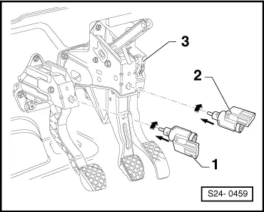
| 30 - | PAS pressure switch -F88- |
|
|