| –
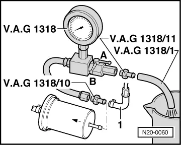
| Disconnect feed line -1- from the fuel filter inlet. |
| –
| Connect pressure gauge -V.A.G 1318 - with the adapter -1318/10 - at the hose. |
| If the minimum delivery volume now reached: |
| If the minimum delivery volume is still not reached: |
| –
| Remove fuel delivery unit ( → Chapter) and inspect the filter strainer for soiling. |
| If you have still not found any fault up to this stage: |
| –
| Fuel pump defective, replace the fuel delivery unit → Chapter. |
| If the required fuel delivery volume has been achieved, but a fault is still suspected in the fuel supply system (e.g. intermittent breakdown of the fuel supply). |
| –
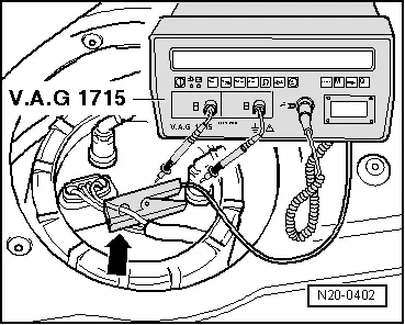
| Check the power consumption of the fuel pump as follows: |
| –
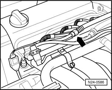
| Connect all released fuel lines. |
| –
| Remove the boot floor cover. |
|
|
|
 WARNING
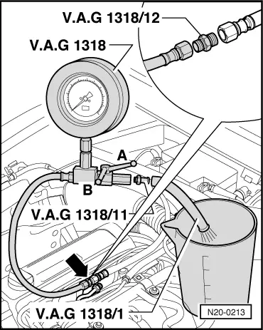
 Note
Note