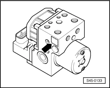
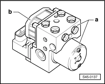
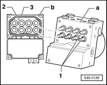
| When tightening the control unit -b- of the hydraulic unit -a- make sure the valve domes -1- are not tilted along with the solenoid coils -2-. |
| 3 - | Gasket made of silicone |
| The gasket is injected and cannot be replaced. The control unit should not be reinstalled if the seal is damaged. |
| –
| Cover the solenoid coils of the control unit. |
| –
| Protect the valve dome from damage and contaminants. Do not use fluffing cloths or a transport protection of an already installed spare part hydraulic pump. This is a requirement for possible guarantee claims. |
| Assembling the hydraulic control unit |
| –
| Inspect the sealing surface on the hydraulic unit for soiling, if necessary clean with white spirits and a non-fluffing paper or linen cloth. |
| –
| If an oily or aqueous film appears on the surface of the hydraulic unit, clean with white spirits and a non-fluffing paper or linen cloth. |
| –
| If there is a considerable oily and aqueous film between the valves use moisture-free and oil-free compressed air to blow it out. |
| –
| If damage is noticed on the hydraulic unit (e.g. scoring or scratching etc.) near the seal, replace the hydraulic unit. |
| –
| Check the gasket of the control unit for tears, roughened surface, elasticity (the gasket must not be hard), notches and a protrusion of 0.1 mm. |
|
| The protrusion is the distance between the lugs in the housing of the control unit and the top side of the gasket. |
|
| The control unit should not be reinstalled if there is anything wrong with the gasket. It is not possible to replace the gasket. |
| –
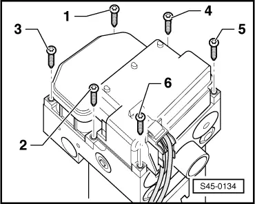
| Compare the length of the screws removed with those in the parts kit (long and short screws, the difference being approx. 15 mm) and determine the correct length of the screws. Never screw long screws into hydraulic control units which have threaded bores for short screws. |

Note | When assembling the control unit and the hydraulic unit make sure the valve domes of the hydraulic unit do not tilt along with the solenoid coils of the control unit. |
| –
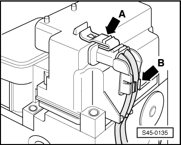
| Place the control unit on the hydraulic unit and guide the solenoid coils over the valves by exerting a slight pressure. While doing so center the control unit relatively to the hydraulic unit. |
| –
| Press by hand on the control unit until it fixes in place with the two centre screws. |
Note | t
| Only use new inner Torx screws from the parts kit. Make sure you use screws of the correct length. |
| t
| Screw on the hydraulic unit and the control unit in the prescribed sequence and in steps. Tightness will not be guaranteed if this is not observed. |
| t
| When screwing together make sure the left and right gap between the control unit and the hydraulic unit is always the same. |
|
|
|