skoda Workshop Repair Guides

Skoda Workshop Service and Repair Manuals

Vacuum pump for the brake servo unit, vacuum pump for the brake V192 , pressure sensor for the brake servo unit G294 > < Repairing the brake caliper
Removing and installing the master brake cylinder with brake servo unit
Special tools and workshop equipment required
t  Release tool -T10159-
t  Brake filling and bleeding device, e.g. -VAS 5234- or -ROMESS S15-
t  Insert -Torx 45- (commercially available)
t  Brake fluid → Chapter
Removing:
–  Remove the storage area on the driver's side → Body Work; Rep. Gr.70
–  Remove brake light switch -F- and brake pedal switch -F47- → Chapter
–  Separating the brake pedal from the brake servo unit → Chapter
  Note
Protect the plenum chamber from brake fluid which is leaking out.
–  Lay sufficient non-fluffing cloths in the plenum chamber in the area of the master brake cylinder.
   
–  Open the stop plugs -arrow- in the brake fluid reservoir.
–  Suck out the brake fluid using the bBrake filling and bleeding device, e. g. -VAS 5234- or -ROMESS S15-
  A47-0137
–  Disconnect plug -1- from the brake fluid level warning contact -F34-.
–  Pull the vacuum hose -2- off the brake servo unit.
  S47-0084
–  Unscrew bolt -1-.
–  Remove the brake fluid reservoir and lay it to one side.
  A47-0140
–  Screw-off the the brake lines -1- on the master brake cylinder and plug up the brake lines using plugs from the repair kit SP No. 1 H0 698 311 A.
–  Loosen nuts -3- somewhat since this eases separation from the master brake cylinder and brake servo unit.
–  Screw out screws -2-, inner torx 45 from the brake servo unit.
–  Remove the brake servo unit with master brake cylinder from the plenum chamber.
  N47-0183
–  Release the nuts -1- of the master brake cylinder.
–  Carefully take the master brake cylinder out of the brake servo unit.
Installing:
Installation is carried out in the reverse order. Pay attention to the following:
–  Check dimension of the spherical head on the brake servo unit, adjust if necessary → Chapter
–  Clipping the brake pedal onto the brake servo unit.
   Hold the spherical head of the push rod in front of the support and press the brake pedal towards the brake servo unit until the spherical head locks audibly into place → Chapter
–  Installing and setting the new brake light switch -F- and brake pedal switch -F47- → Chapter
–  Bleeding Brake System → Chapter
–  Bleed clutch unit → manual gearbox; Rep. Gr.30
–  Perform test drive after the bleeding of air with at least one ABS adjustment.
  A47-0054
Tightening torques:
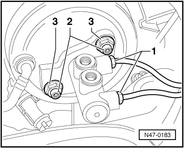
Brake lines to hydraulic unit
Brake lines to master brake cylinder
Brake lines to brake caliper
 
Thread M10 x 114 Nm
Thread M12 x 1 SW 1114 Nm
Thread M12 x 1 SW 12 - up to 01.0324 Nm
Thread M12 x 1 SW 12 - as of 02.0316 Nm
t  Always tighten to 16 Nm when installing a new brake line M12 x 1 SW 12
 
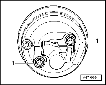
Master brake cylinder to brake servo unit
t  Use new nuts!
49 Nm
The master brake cylinder with brake servo unit on the rear wall and the foot controls25 Nm
Brake fluid reservoir on the master brake cylinder9 Nm

  Note
Always tighten to 16 Nm when replacing a new brake line M12 x 1.
   

Vacuum pump for the brake servo unit, vacuum pump for the brake V192 , pressure sensor for the brake servo unit G294 > < Repairing the brake caliper