
Superb
 Note
Note| t | As of gearbox manufacturing date 06.03, a new 3-pin synchronization for the 1st gear and a 2-pin synchronization for the 2nd gear as well as synchronizer rings with enlarged friction cone and reduced engaging gearing for 5th gear and reverse gear is used. The sliding gears, sliding sleeves and synchronizer bodies were adapted equivalently and cannot be fitted with synchronizer parts of old fitting status. |
| t | When installing new pinions or a drive shaft observe the technical data → Chapter and → Electronic Catalogue of Original Parts. |
| t | In case of replacement of the parts marked with 1) the adjustments need to be made. Setting overview → Chapter. |

| 1 - | Gearbox housing1) |
| q | is made out of aluminium or magnesium → Chapter |
| 2 - | Adjusting washer S3 |
| q | Setting overview → Chapter |
| 3 - | Outer ring/taper roller bearing, large1) |
| q | removing → Fig. |
| q | installing → Fig. |
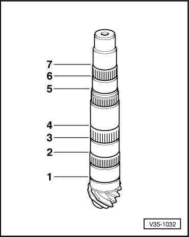
| 4 - | Secondary shaft (output shaft)1) |
| q | is paired with the crown wheel, replace together |
| q | Adjusting the secondary shaft and crown wheel → Chapter |
| 5 - | Inner ring/taper roller bearing, large1) |
| q | is damaged when removing |
| q | replace → Electronic Catalogue of Original Parts |
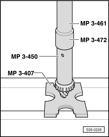
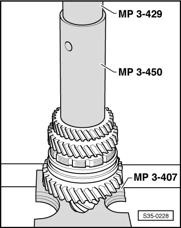
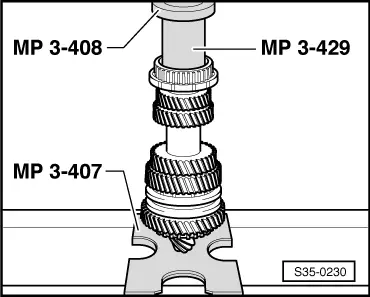
| q | pressing off → Fig. |
| q | pressing on → Fig. |
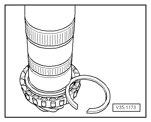
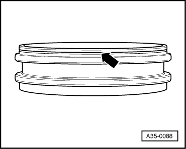
| 6 - | Circlip |
| q | mark |
| q | Fitting position → Fig., Pos. 1 |
| q | if replacing the tapered-roller bearing, determine again → Fig. |
| 7 - | for 1st gear needle bearing |
| 8 - | 1st gear sliding gear |
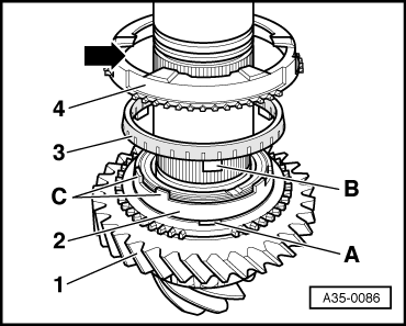
| 9 - | Inner ring for 1st gear |
| q | Fitting position → Fig. |
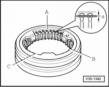
| q | check for wear → Fig. |
| q | replace if there are any traces of scoring or of friction |
| 10 - | Intermediate ring for 1st gear |
| q | Fitting position → Fig. |
| q | check for wear → Fig. |
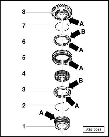
| 11 - | 1st gear synchronizer ring |
| q | Fitting position → Fig. |
| q | check for wear → Fig. |
| q | replace if there are any traces of scoring or of friction |
| 12 - | Sliding sleeve 1st and 2nd gear |
| q | Mark installation position |
| q | Assemble sliding sleeve and synchronizer body → Fig. |
| 13 - | Pressure plate |
| q | Install pressure plates (3 pieces) → Fig. |
| 14 - | Synchronizer body 1st and 2nd gear |
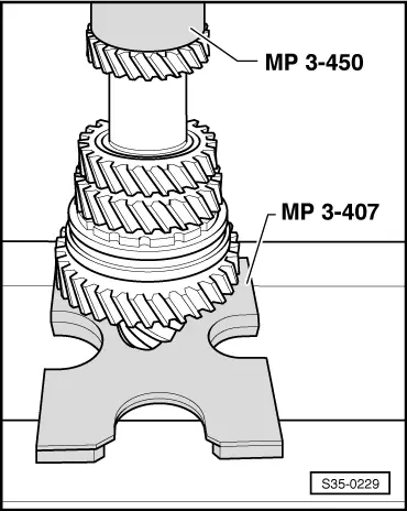
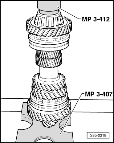
| q | pressing off → Fig. |
| q | high collar points to the 2nd gear |
| q | pressing on → Fig. |
| q | Assemble sliding sleeve and synchronizer body → Fig. |
| 15 - | Circlip |
| q | mark |
| q | Fitting position → Fig., Pos. 2 |
| q | if replacing the synchronizer body, determine again → Fig. |
| 16 - | for 2nd gear needle bearing |
| 17 - | 2nd gear synchronizer ring |
| q | Fitting position → Fig. |
| q | check for wear → Fig. |
| q | replace if there are any traces of scoring or of friction |
| 18 - | Intermediate ring for 2nd gear |
| q | Fitting position → Fig. |
| q | check for wear → Fig. |
| 19 - | Inner ring for 2nd gear |
| q | Fitting position → Fig. |
| q | check for wear → Fig. |
| q | replace if there are any traces of scoring or of friction |
| 20 - | 2nd gear sliding gear |
| 21 - | Circlip |
| q | mark |
| q | Fitting position → Fig., Pos. 3 |
| 22 - | 3rd gear pinion |
| q | pressing off → Fig. |
| q | Groove points to the 4th gear |
| q | pressing on → Fig. |
| 23 - | Circlip |
| q | mark |
| q | Fitting position → Fig., Pos. 4 |
| q | if replacing the 3rd gear pinion, determine again → Fig. |
| 24 - | 4th gear pinion |
| q | pressing off → Fig. |
| q | Collar points to the 3rd gear |
| q | pressing on → Fig. |
| 25 - | Circlip |
| q | mark |
| q | Fitting position → Fig., Pos. 5 |
| q | if replacing the 4th gear pinion, determine again → Fig. |
| 26 - | Needle bearing |
| 27 - | 5th gear sliding gear |
| q | Distinguishing feature → Fig. |
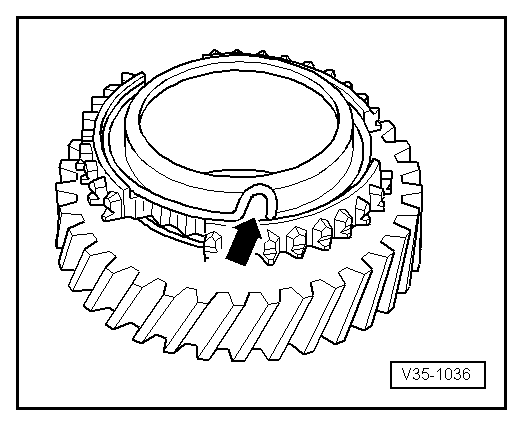
| 28 - | Spring |
| q | Modification feature → Fig. |
| q | place in the 5th gear sliding gear → Fig. |
| q | Assignment to sliding gear → Electronic Catalogue of Original Parts |
| 29 - | 5th gear synchronizer ring |
| q | Modification feature → Fig. |
| q | check for wear → Fig. |
| 30 - | Circlip |
| q | mark |
| q | Fitting position → Fig., Pos. 6 |
| 31 - | 5th gear synchronizer body and reverse gear |
| q | Modification feature → Fig. |
| q | pressing off → Fig. |
| q | Collar points to the 5th gear sliding gear |
| q | pressing on → Fig. |
| 32 - | Circlip |
| q | mark |
| q | Fitting position → Fig., Pos. 5 |
| q | if replacing the 5th gear synchronizer body and reverse gear, determine again → Fig. |
| 33 - | Needle bearing |
| q | for reverse gear |
| 34 - | Sliding sleeve for 5th gear and reverse gear |
| q | Modification feature → Fig. |
| q | Fitting position: groove points to the 5th gear sliding °gear → Fig. |
| 35 - | Reverse gear synchronizer ring |
| q | Modification feature → Fig. |
| q | check for wear → Fig. |
| 36 - | Spring |
| q | Modification feature → Fig. |
| q | position in the reverse gear sliding gear → Fig. |
| q | Assignment to sliding gear → Electronic Catalogue of Original Parts |
| 37 - | Reverse gear sliding gear |
| q | Modification feature → Fig. |
| 38 - | Inner ring/taper roller bearing, small1) |
| q | pressing off → Fig. |
| q | pressing on → Fig. |
| 39 - | Bush |
| q | for securing small outer ring/taper roller bearing |
| q | removing → Fig. |
| q | after replacing the small tapered-roller bearing it does no longer have to be installed |
| 40 - | Outer ring/taper roller bearing, small1) |
| q | removing → Fig. |
| q | installing → Fig. |
| 41 - | Adjusting washer S4 |
| q | Setting overview → Chapter |
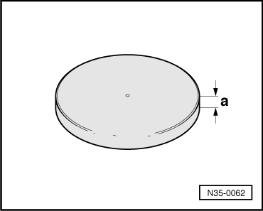
| 42 - | Pressure plate |
| q | different thickness for gearbox made out of aluminium and magnesium → Fig. |
| 43 - | Rubber washer |
| q | for linear compensation |
| q | to remove, drill a hole into the washer, screw in sheet metal screw and pull out at the sheet meet screw. |
| q | different thickness for gearbox made out of aluminium and magnesium → Fig. |
| q | Assign the components by gearbox code letters via the → electronic catalogue of original parts. |
| 44 - | Gearbox cover |
| q | made out of aluminium, must only be fitted with gearbox housing out of aluminium |
| q | made out of magnesium, must only be fitted with gearbox housing out of magnesium |
| q | Pay attention to the marking → Chapter |
| q | Thinly coat sealing surfaces with sealant -AMV 188 001 02- |
Note
|
|
|
|
|
|
|
|
|
|
|
|
|
|
|
|
|
|
Note
|
|
|
|
|
|
|
|
|
|
Note
|
|
| Circlip thickness (mm) | ||
| 2,00 | 2,06 | 2,12 |
| 2,03 | 2,09 | 2,15 |
|
| Circlip thickness (mm) | ||
| 1,90 | 1,96 | 2,02 |
| 1,93 | 1,99 | |
|
| Circlip thickness (mm) | ||
| 2,50 |
|
| Circlip thickness (mm) | ||
| 1,90 | 1,98 | 2,06 |
| 1,94 | 2,02 | |
|
| Circlip thickness (mm) | ||
| 1,86 | 1,94 | |
| 1,90 | 1,98 | |
|
| Circlip thickness (mm) | ||
| 2,00 |
|
| Circlip thickness (mm) | ||
| 1,90 | 1,96 | 2,02 |
| 1,93 | 1,99 | 2,05 |
Note
|
|
|
|
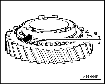
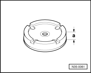
| Clearance “a” | Installed size new | Wear limit |
| 1st °gear - Inner ring | 1.2…2.0 mm | 0.6 mm |
|
|
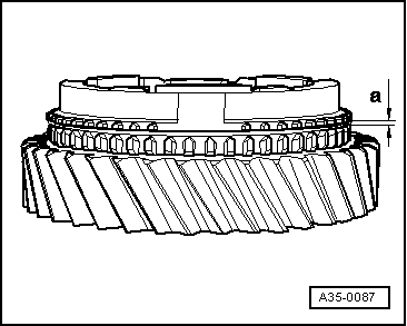
| Clearance “a” | Installed size new | Wear limit |
| 1. and 2nd gear | 1.4…2.0 mm | 0.8 mm |
|
|
|
|
|
|
|
|
|
|
|
|
|
|
|
|
|
|
|
|
| Dimension -a- | |
| for gearbox made out of aluminium | 14.8 mm or 15.3 mm |
| for gearbox made out of magnesium | 10.7 mm |
|
|
| Dimension -a- | |
| for gearbox made out of aluminium | 7 mm |
| for gearbox made out of magnesium | 11 mm |