
XT-6 2WD L6-2.7L SOHC (1989)
12.
On manual transmission equipped vehicles, remove clutch pressure plate and disc.
13.
Remove flywheel or driveplate, then the flywheel housing.
14.
Remove cylinder heads as previously described.
15.
Remove oil pan attaching bolts, then the oil pan. Do not remove oil strainer from crankcase.
16.
Remove oil separator cover from rear of crankcase.
17.
Remove service access plugs from both sides of front of crankcase.
18.
Rotate crankshaft until pistons for No. 1 and No. 2 cylinders are at BDC.
19.
Working through access holes, remove piston pin circlips for No. 1 and No. 2 pistons.
20.
Using piston pin remover 499097300 or equivalent, withdraw piston pins for No. 1 and No. 2 pistons.
21.
Repeat steps 17 through 19 for cylinders 5 and 6 and 3 and 4 respectively.
22.
Remove all crankcase half retaining bolts except the one bolt for No. 3 cylinder.
23.
Position crankcase so that cylinders 1, 3 and 5 face upward, then separate crankcase halves, Fig. 25.
24.
Remove coolant passage O-ring and back-up ring from crankcase, then the front and rear oil seals from crankshaft.
25.
Remove crankshaft and connecting rod assembly.
26.
Mark and remove pistons from crankcase halves, and mate pistons with respective pins. Keep all components in order to ensure proper
assembly. Components that are to be reused should be installed in original position.
27.
Remove main bearings from crankcase halves.
28.
Ensure all components are clean and free from foreign material, and that oil passages are clear. Coat all friction surfaces with oil or suitable
assembly lubricant.
29.
Connecting Rod installation:
a. Seat bearings in connecting rods and rod caps, then install connecting rods to crankshaft.
b. Ensure connecting rod and cap matching marks are aligned, and install connecting rod assemblies with crescent shaped mark facing forward.
c. Lubricate connecting rod bolt threads and ensure bolts are properly seated in cap and that caps are fully seated against connecting rods.
d. Evenly torque connecting rod nuts to specifications.
30.
Install main bearings into crankcase halves.
31.
Install crankshaft into lefthand crankcase, then fit O-ring and back-up ring to crankcase coolant passage.
32.
Clean crankcase half mating surfaces with suitable solvent, then apply a thin bead of Three-Bond 1215 sealant or equivalent to one crankcase half.
Ensure sealant does not enter oil or coolant passages.
33.
Guide righthand crankcase half onto left case, then install retaining bolts and torque to specifications shown in Fig. 25. Ensure O-ring is correctly
positioned in groove.
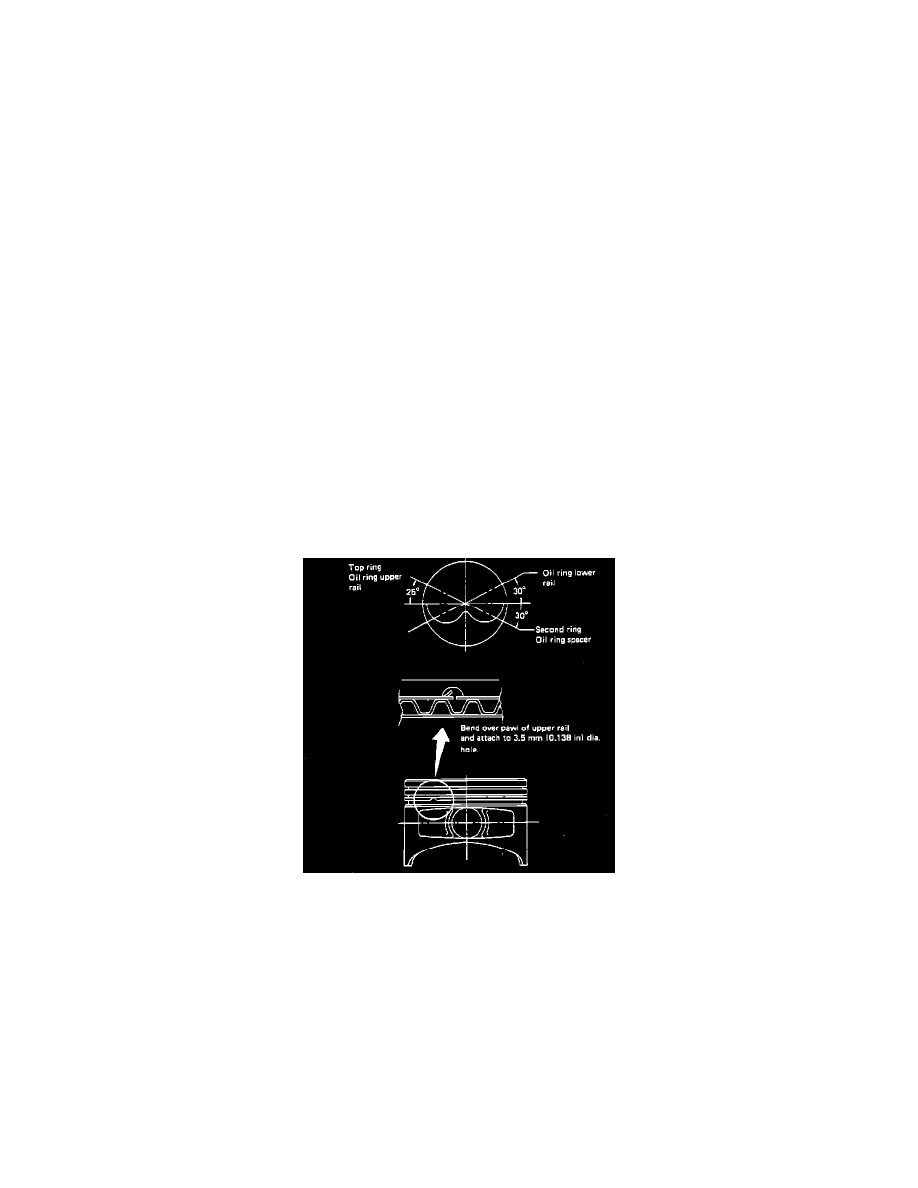
Fig. 10 Piston Ring Installation
34.
Install piston rings onto pistons, positioning end gaps as shown, Fig. 10. After installation, bend pawl of upper oil ring rail upward and attach to
hole in piston, Fig. 10.
35.
Piston installation:
a. With No. 5 and 6 cylinders facing downward, turn crankshaft until No. 3 and 4 connecting rods are positioned at BDC.
b. Insert No. 4 piston into cylinder, align piston pin hole and connecting rod small end with pin guide 499017000 or equivalent, then install
piston pin through access hole.
c. Install piston pin circlip, ensuring ends face outward.
d. Install remaining pistons in the following order: Nos. 3, 1, 2, 5 and 6. Ensure connecting rods are positioned at BDC before installation, and
that circlip ends face outward.
36.
Coat service access hole plug threads with Three-Bond 1205 sealant or equivalent, then install plugs using new gasket and tighten to
specifications.
37.
Coat outside surface of front and rear seals with engine oil, and seal lips with grease, then install front and rear oil seals using suitable tool.
38.
Install oil separator cover using new gasket. Tighten to specifications.