
Sidekick 4WD L4-1590cc 1.6L SOHC 0 TBI 8V (1990)
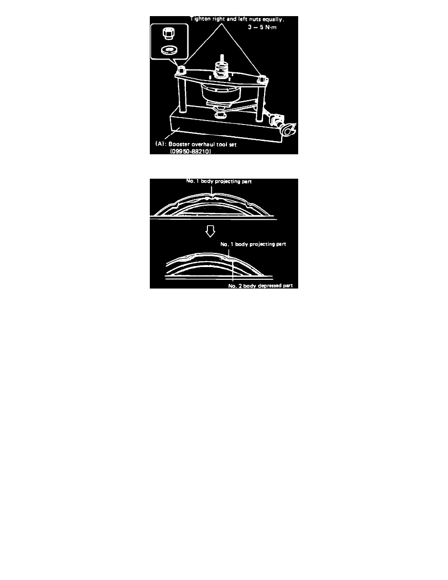
Fig. 4 Separating Booster Bodies
Fig. 5 Booster Body Alignment Marks
Refer to Figs. 1 through 3, when performing this procedure.
1.
Remove piston rod from booster, then push rod clevis and nut.
2.
Set booster in booster overhaul set No. 09950-88210, Fig. 4.
3.
Tighten tool bolt clockwise until No. 1 body projecting part and No. 2 body depressed part fit each other, Fig. 5. Mark both body parts.
4.
Remove booster from tool, then separate No. 1 and No. 2 bodies. Hold both bodies carefully to prevent either body from jumping off by
spring force.
5.
Remove piston return spring.
6.
From No. 2 body, remove boot, air cleaner elements and air cleaner separator.
7.
On Sidekick models, remove valve stopper key cushion from stopper key.
8.
On Samurai models, using camshaft pulley holder No. 09917-68210 or equivalent, remove booster piston.
9.
On all models, while compressing air valve spring, remove valve stopper key, then the booster air valve assembly. Air valve assembly can not
be disassembled.
10.
On Sidekick models, remove diaphragm circular ring from booster piston.
11.
On Samurai models, remove diaphragm from pressure plate.
12.
On Sidekick and Swift models, remove diaphragm from booster piston.
13.
On all models, remove reaction disc from booster piston.
14.
On Samurai models, using oil seal replacers No. 09951-08210 and No. 09951-18210 or equivalents, remove oil seal from No. 2 body.
15.
On Sidekick and Swift models, using oil seal replacers No. 09951-16020 and No. 09951-18210 or equivalents, remove oil seal from No. 2 body.
16.
On all models, reverse procedure to assemble. Check brake pedal height and pedal travel as outlined under ADJUSTMENT
PROCEDURES/BRAKE PEDAL HEIGHT and BRAKE PEDAL TRAVEL CHECK.