
SX4 2WD L4-2.0L (2007)
Installation
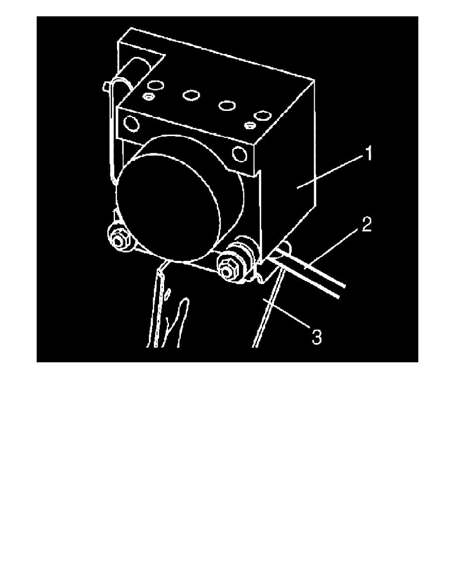
1. Install ABS (ESP(R)) Hydraulic unit / control module assembly by reversing removal procedure noting the following.
Install ABS (ESP(R)) hydraulic unit / control module assembly bracket bolt as follows.
a) Tighten bracket bolt (1) and (2) by hand.
b) Then tighten bracket bolt to specified torque.
Tightening order (1)-(2)
Note:
Brake pipe flare nuts (3) from master cylinder is attached M10 nut (ABS model) or M12 (ESP(R) model).
Tightening torque
Brake pipe flare nut for M10 (a): 16 Nm (1.6 kg.m, 11.5 ft. lbs.)
Brake pipe flare nut for M12 (b): 19 Nm (1.9 kg.m, 14.0 ft. lbs.)
ABS hydraulic unit / control module assembly bolt (c): 9 Nm (0.9 kg.m, 6.5 ft. lbs.)
ABS hydraulic unit / control module assembly bracket bolt (d): 26 Nm (2.6 kg.m, 19.0 ft. lbs.)