
SX4 4WD L4-2.0L (2008)
Engine Control Module: Component Tests and General Diagnostics
ECM Power and Ground Circuit Check
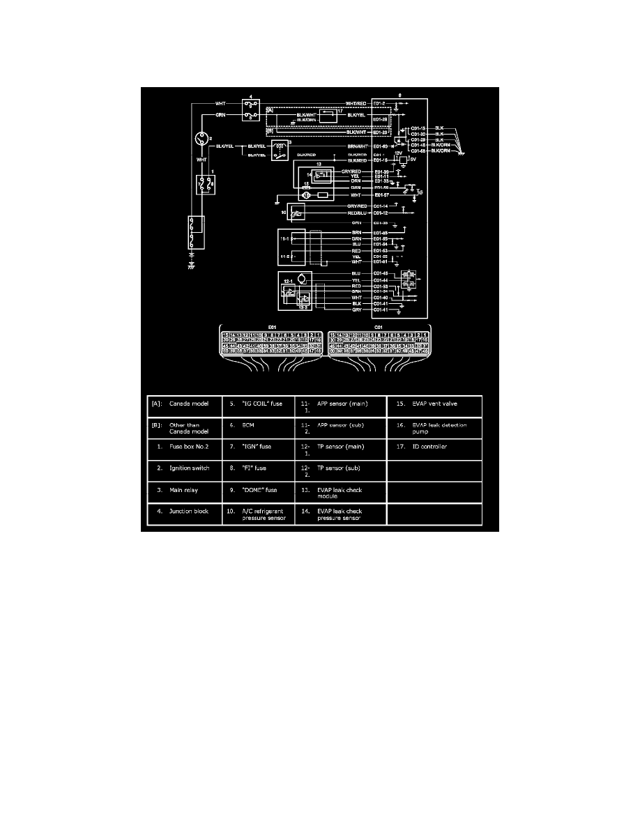
Wiring Diagram
Wiring Diagram
Circuit Description
When the ignition switch is turned ON, the main relay turns ON (the contact point closes) and the main power is supplied to ECM. And then ECM
supplies 5 V power to each sensor (EVAP leak check pressure sensor, A/C refrigerant pressure sensor, APP sensor and TP sensor). If 5 V power circuit
to each sensors from ECM is shorted to ground, ECM stops engine and emission control operation.
Troubleshooting
NOTE:
^
Before performed troubleshooting, be sure to read the Precautions of ECM Circuit Inspection.
^
When measuring circuit voltage, resistance and/or pulse signal at ECM connector, connect the special tool to ECM and/or the ECM connectors
referring to Inspection of ECM and Its Circuits. See: Powertrain Management/Computers and Control Systems/Testing and Inspection/Pinout
Values and Diagnostic Parameters