
XL-7 2WD V6-3.6L (2007)
Circuit/System Description
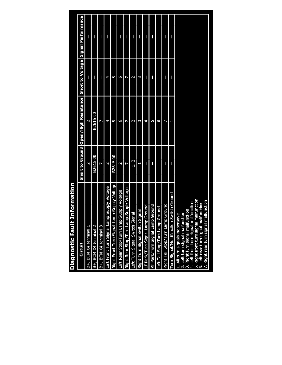
Ground is applied at all times to the turn signal/multifunction switch from G201. The turn signal lamps may only be activated with the ignition switch in
the ON position. The body control module (BCM) controls the vehicle turn signals based on inputs from the turn signal/multifunction switch. With the
turn signal/multifunction switch in either the left or right turn position, a ground is applied through the turn signal switch signal circuit to the BCM
indicating a turn signal request. When the specific request is seen, the BCM then applies a pulsating voltage through the front and rear turn signal supply
voltage circuits illuminating the turn signal lamps.
When a turn signal request is seen by the BCM, a serial data message is sent to the instrument panel cluster (IPC) requesting the respective turn signal
indicator be pulsed.
Circuit/System Verification
1. Ignition ON, observe the scan tool Left Turn Signal Switch parameter while using the turn signal/multifunction switch to turn the left turn signal
on and off. The parameter should cycle between Active and Inactive.
^
If the parameter does not cycle between the specified values, refer to Turn Signal/Multifunction Switch Circuit Test.