
XL-7 2WD V6-3.6L (2007)
Turn Signal Indicator: Testing and Inspection
Turn Signal Lamps and/or Indicators Always on or Flashing
Turn Signal Lamps and/or Indicators Always On or Flashing
Diagnostic Instructions
^
Perform the [Diagnostic System Check - Vehicle Diagnostic Information] prior to using this diagnostic procedure. See: Testing and
Inspection/Initial Inspection and Diagnostic Overview/Diagnostic System Check - Vehicle Diagnostic Information
^
[Strategy Based Diagnosis]See: Testing and Inspection/Initial Inspection and Diagnostic Overview/Strategy Based Diagnosis
^
[Diagnostic Procedure Instructions - Vehicle Diagnostic Information].See: Testing and Inspection/Initial Inspection and Diagnostic
Overview/Diagnostic Procedure Instructions - Vehicle Diagnostic Information
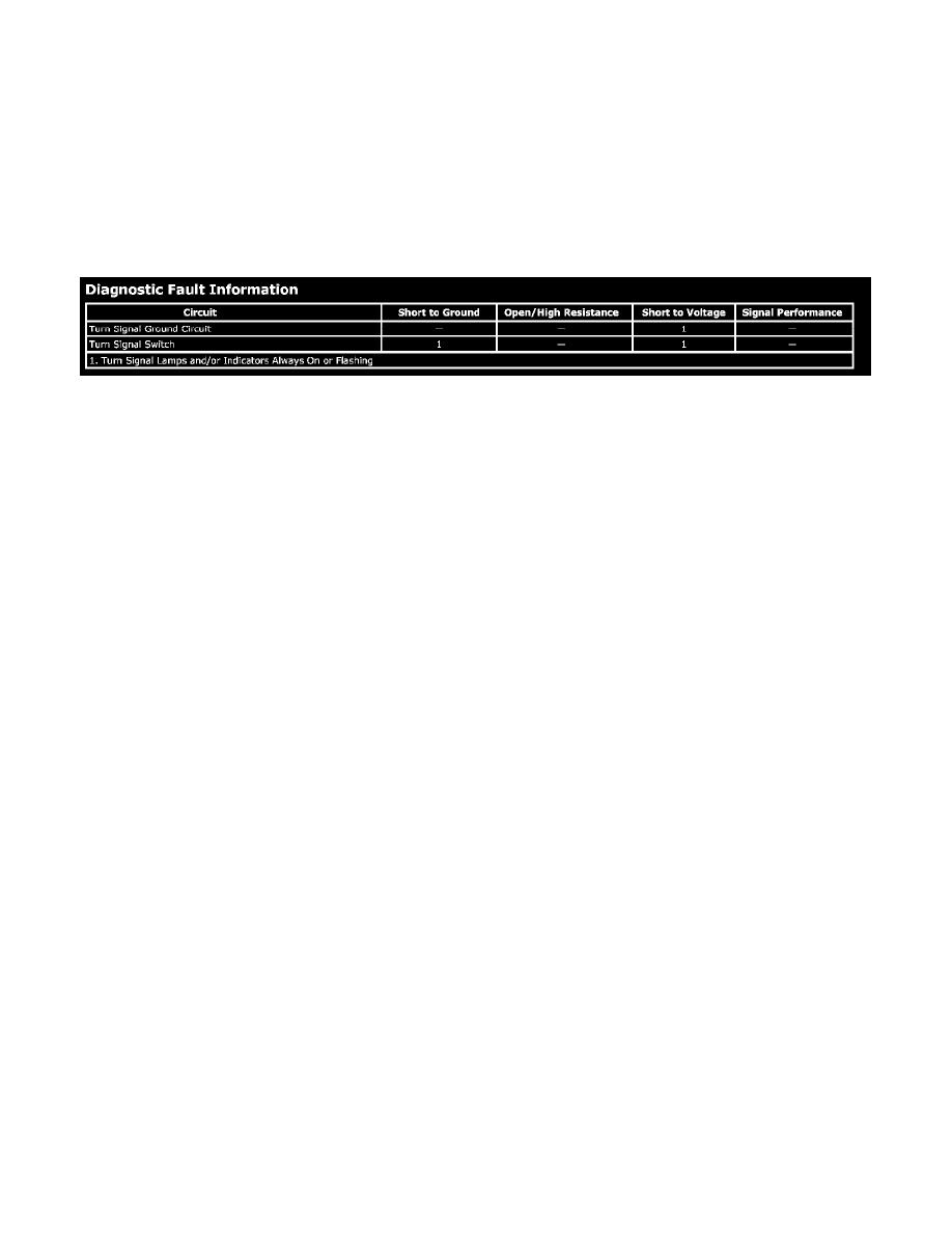
Diagnostic Fault Information
Circuit/System Description
Voltage runs through the left and right turn signal fuses of the instrument panel I/P fuse block, then through the body control module BCM, before
reaching the turn signal multifunction switch. When the turn signal switch is engaged, the switch closes and supplies voltage to the front and rear
park/turn signal lamps.
Diagnostic Aids
^
There are certain relays that are PCB or soldered to the underhood fuseblock circuit board and any relay replacement would warrant a replacement
of the underhood fuseblock.
^
This vehicle is not equipped with a turn signal relay.
^
An open/high resistance or a short to ground in the turn signal multifunction switch would cause the turn signal lamps to always be ON or
continually flashing.
Circuit/System Verification
Ignition ON, observe the right or left turn signal while engaging the turn signal multifunction switch in the appropriate position.
Circuit/System Testing
1. Ignition OFF, disconnect the harness connector at the turn signal multifunction switch.
2. Test for less than 5 ohms of resistance between the ground circuit and ground.
^
If greater than 5 ohms, test the ground circuit for an open/high resistance.
3. Install a 3-amp fused jumper wire between the signal circuit and ground. Verify that the proper turn signal lamp is ON.
^
If the turn signals are not ON, test the left and right signal circuit of the turn signal multifunction switch for a short to voltage or an open/high
resistance.
4. If all circuits test normal, test or replace the turn signal multifunction switch.
Component Testing
1. Ignition OFF, disconnect the harness connector at the turn signal multifunction switch.
2. Test for infinite resistance between the signal terminal and the voltage supply terminal with the switch in the open position.
^
If less than infinite resistance, replace the turn signal multifunction switch.
3. Test for less than 1.5 ohms between the signal terminal and the voltage supply terminal with the switch in the closed position.
^
If greater than 1.5 ohms, replace the turn signal multifunction switch.
Repair Instructions
Perform the [Diagnostic Repair Verification - Vehicle Diagnostic Information] after completing the diagnostic procedure. See: Testing and
Inspection/Diagnostic Trouble Code Tests and Associated Procedures
^
[Hazard Warning Switch Replacement]
^
[Turn Signal Multifunction Switch Replacement]