
XL-7 2WD V6-3.6L (2007)
9. If the clock location of the high spot has moved, however the assembly runout has NOT bee reduced, perform the following steps:
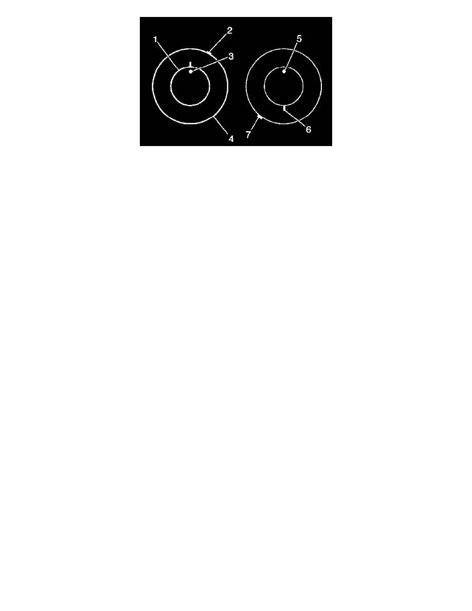
a. If the clock location of the high spot (7) is now at or near a position 180 degrees from the original clock location of the high spot, the tire is
the major contributor to the assembly runout concern.
b. If the clock location of the high spot is now in-between the 2 extremes, then both the tire and the wheel are both contributing to the assembly
runout concern. Rotate the tire an additional 90 degrees in both the clockwise and the counterclockwise directions to obtain the lowest
amount of assembly runout.
Tire and Wheel Assembly-to-Hub/Axle Flange Match Mounting
Tire and Wheel Assembly-to-Hub/Axle Flange Match Mounting
NOTE:
After remounting a tire and wheel assembly to a hub/axle flange, remeasure the tire and wheel assembly on-vehicle runout in order to verify that the
amount of runout has been reduced and brought to within tolerances.
1. Mark the location of the high spot on the tire and wheel assembly as determined during the on-vehicle tire and wheel assembly runout
measurement.
2. Place a reference mark on the wheel stud that is located closest to the wheel valve stem.
^
Always refer to the reference mark on the wheel stud as the 12 o'clock position.
^
Refer to the location of the high spot by its clock position on the tire and wheel assembly, relative to the marked wheel stud.
3. Remove the tire and wheel assembly from the hub/axle flange.
4. Rotate the tire and wheel assembly as close to 180 degrees as possible on the hub/axle flange, so that the wheel valve stem is now approximately
at the 6 o'clock position in relation to the marked wheel stud.
5. Reinstall the wheel lug nuts to secure the tire and wheel assembly in the new position.
6. Remeasure the tire and wheel assembly on-vehicle runout. Mark the new location of the assembly on-vehicle runout high spot on the tire.
7. If the assembly on-vehicle runout has been reduced and is within tolerance, no further steps are necessary.
8. If the assembly runout has NOT been reduced, perform the following steps:
a. If the clock location of the high spot remained at or near the original clock location of the high spot, the hub/axle flange and/or the brake
rotor/drum mounting flange is the major contributor to the assembly on-vehicle runout concern.
b. If the clock location of the high spot is now at or near a position 180 degrees from the original clock location of the high spot, the tire and
wheel assembly is the major contributor to the assembly on-vehicle runout concern.
c. If the clock location of the high spot is now in-between the 2 extremes, then both the tire and wheel assembly and the hub/axle flange are
contributing to the assembly on-vehicle runout concern. Rotate the tire and wheel assembly as close to an additional 90 degrees as possible in
both the clockwise and the counterclockwise directions to obtain the lowest amount of assembly on-vehicle runout.