
XL-7 2WD V6-3.6L (2007)
Information Bus: Symptom Related Diagnostic Procedures
Symptoms - Data Communications
Symptoms - Data Communications
NOTE: The following steps must be completed before using the symptom tables.
1. Perform the [Diagnostic System Check - Vehicle Diagnostic Information] See: Testing and Inspection/Initial Inspection and Diagnostic
Overview/Diagnostic System Check - Vehicle Diagnostic Information before using the symptom tables in order to verify that all of the following
are true:
^
There are no DTCs set.
^
The control modules can communicate via the serial data links.
2. Review the system operation in order to familiarize yourself with the system functions. Refer to [Data Link Communications Description and
Operation].
Visual/Physical Inspection
^
Inspect for aftermarket devices which could affect the operation of the systems.
^
Inspect the easily accessible or visible system components for obvious damage or conditions which could cause the symptom.
Intermittent
Faulty electrical connections or wiring may be the cause of intermittent conditions. Refer to [Testing for Intermittent Conditions and Poor Connections in
Diagnostic Aids]. See: Diagrams/Diagnostic Aids
Symptom List
Refer to a symptom diagnostic procedure from the following list in order to diagnose the symptom:
^
[Scan Tool Does Not Power Up]
^
[Scan Tool Does Not Communicate with High Speed GMLAN Device]
^
[Scan Tool Does Not Communicate with Low Speed GMLAN Device]
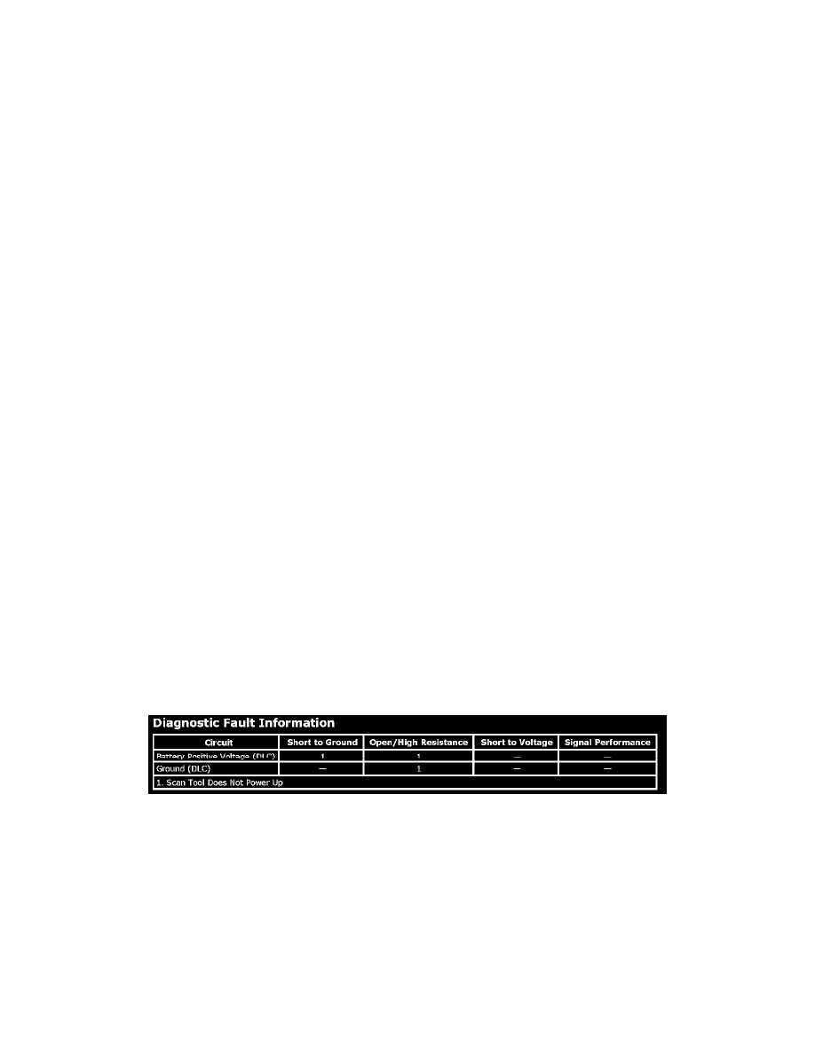
Scan Tool Does Not Power Up
Scan Tool Does Not Power Up
Diagnostic Instructions
^
Perform the [Diagnostic System Check - Vehicle Diagnostic Information] prior to using the diagnostic procedure. See: Testing and
Inspection/Initial Inspection and Diagnostic Overview/Diagnostic System Check - Vehicle Diagnostic Information
^
Review [Strategy Based Diagnosis] for an overview of the diagnostic approach. See: Testing and Inspection/Initial Inspection and Diagnostic
Overview/Strategy Based Diagnosis
^
[Diagnostic Procedure Instructions - Vehicle Diagnostic Information] provides an overview of each diagnostic category. See: Testing and
Inspection/Initial Inspection and Diagnostic Overview/Diagnostic Procedure Instructions - Vehicle Diagnostic Information
Diagnostic Fault Information
Circuit/System Description
The data link connector (DLC) is a standardized 16 cavity connector. Connector design and location is dictated by an industry wide standard, and is
required to provide the following:
^
Scan tool power battery positive voltage at terminal 16
^
Scan tool power ground at terminal 4
^
Common signal ground at terminal 5
Diagnostic Aids
^
The scan tool will power up with the ignition OFF. Some modules however, will not communicate unless the ignition is ON and the power mode
master (PMM) module sends the appropriate power mode message.
^
If the battery positive voltage, ground circuits and connections of the DLC are functioning properly, the malfunction must be due to the scan
tool/CANdi module.