
XL-7 2WD V6-3.6L (2007)
Circuit/System Testing
1. Ignition ON, test for battery voltage between the battery positive voltage circuit of the DLC and ground.
^
If less than battery voltage, repair the voltage supply circuit for a short to ground or an open/high resistance.
2. Test for less than 1 ohm of resistance between the ground circuit of the DLC and ground.
^
If greater than 1 ohm, repair the ground circuit for an open/high resistance.
3. If all tests normal, refer to the scan tool/CANdi module user guide.
Scan Tool Does Not Communicate With High Speed GMLAN Device
Scan Tool Does Not Communicate with High Speed GMLAN Device
Diagnostic Instructions
^
Perform the [Diagnostic System Check - Vehicle Diagnostic Information] prior to using this diagnostic procedure. See: Testing and
Inspection/Initial Inspection and Diagnostic Overview/Diagnostic System Check - Vehicle Diagnostic Information
^
Review [Strategy Based Diagnosis] for an overview of the diagnostic approach. See: Testing and Inspection/Initial Inspection and Diagnostic
Overview/Strategy Based Diagnosis
^
[Diagnostic Procedure Instructions - Vehicle Diagnostic Information] provides an overview of each diagnostic category. See: Testing and
Inspection/Initial Inspection and Diagnostic Overview/Diagnostic Procedure Instructions - Vehicle Diagnostic Information
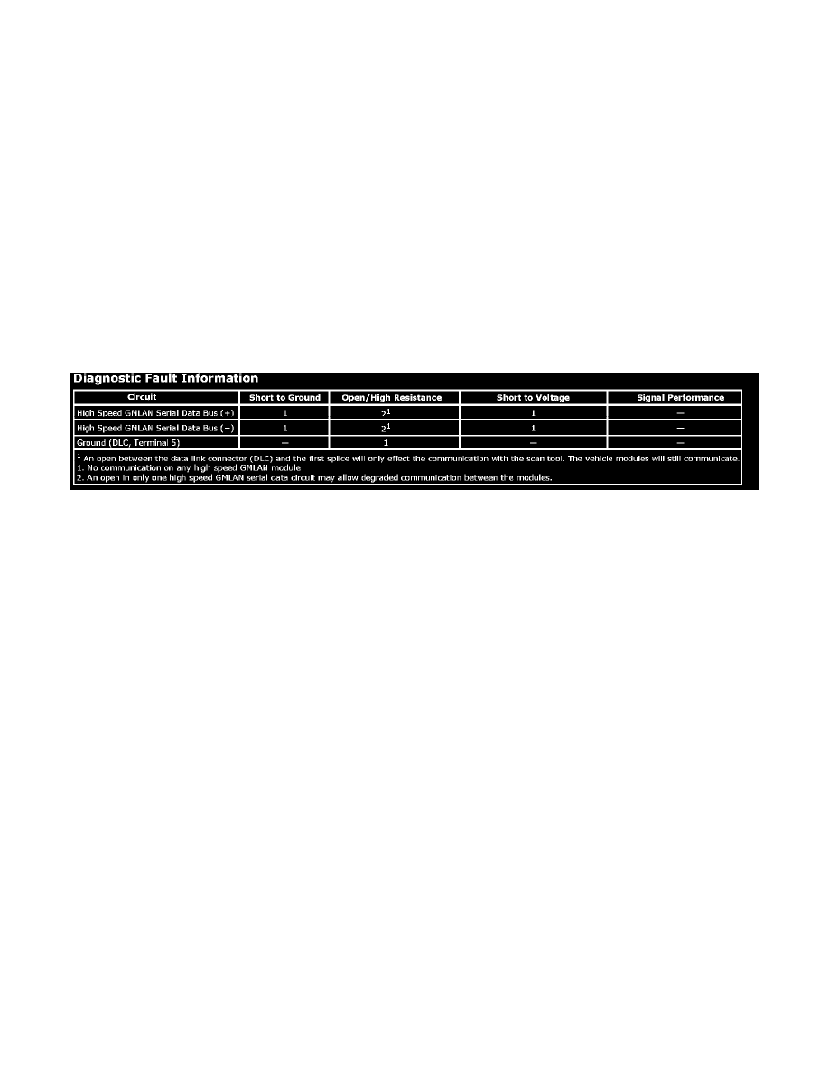
Diagnostic Fault Information
Circuit/System Description
Modules connected to the high speed GMLAN serial data circuits monitor for serial data communications during normal vehicle operation. Operating
information and commands are exchanged among the modules when the ignition switch is in any position other than OFF. The high speed GMLAN serial
data circuits must be operational for the vehicle to start due to body control module (BCM) and engine control module (ECM)/powertrain control
module (PCM) communications. The theft deterrent module and ECM/PCM exchange information using the BCM as the gateway module allowing
communication between the high and low speed serial data busses. The low speed GMLAN serial data circuit must also be operational for vehicle
starting.
Diagnostic Aids
^
Use the [Data Link References] to identify the high speed GMLAN serial data modules.
^
This test is used for a total high speed GMLAN communication failure. If only one module is not communicating and sets no DTC, ensure that the
vehicle is equipped with the module, then use DTC U0100 U0299 for diagnostics.
^
An open in the DLC ground circuit terminal 5 will allow the scan tool to operate to set up the vehicle on the tool and then not communicate with
the vehicle. When the scan tool is to the point of communicating with the vehicle, a message on the scan tool will indicate no CANdi module
detected and will not communicate.
^
The engine will not start when there is a total malfunction of the high speed GMLAN serial data bus. The following conditions may cause a total
loss of high speed GMLAN data communication:
^
A short between high speed GMLAN (+) and high speed GMLAN (-) circuits
^
Any of the high speed GMLAN serial data circuits shorted to ground or voltage
^
A module internal malfunction that causes a short to voltage or ground on the high speed GMLAN circuits
Circuit/System Testing
1. Test for less than 1 ohm of resistance between the DLC ground circuit terminal 5 and ground.
^
If greater than 1 ohm, test the ground circuit for open/high resistance.
2. Ignition OFF, disconnect the harness connector of the BCM.
3. Ignition ON, test for battery voltage between each voltage input circuit of the BCM and ground.
^
If less than battery voltage, test each voltage output circuit of the BCM for a short to ground, and each voltage input circuit of the BCM for a
short to ground or and open/high resistance. If the circuits test normal, replace the faulty module.
4. Test for less than 1 ohm of resistance between each ground circuit of the BCM and ground.
^
If greater than 1 ohm, repair the ground circuit for an open/high resistance.