
XL-7 2WD V6-3.6L (2007)
12. While holding the stabilizer link with a wrench, remove the stabilizer link-to-lower control arm nut.
13. Remove the trailing arms.
14. Remove the adjustment links.
15. Remove the coil springs.
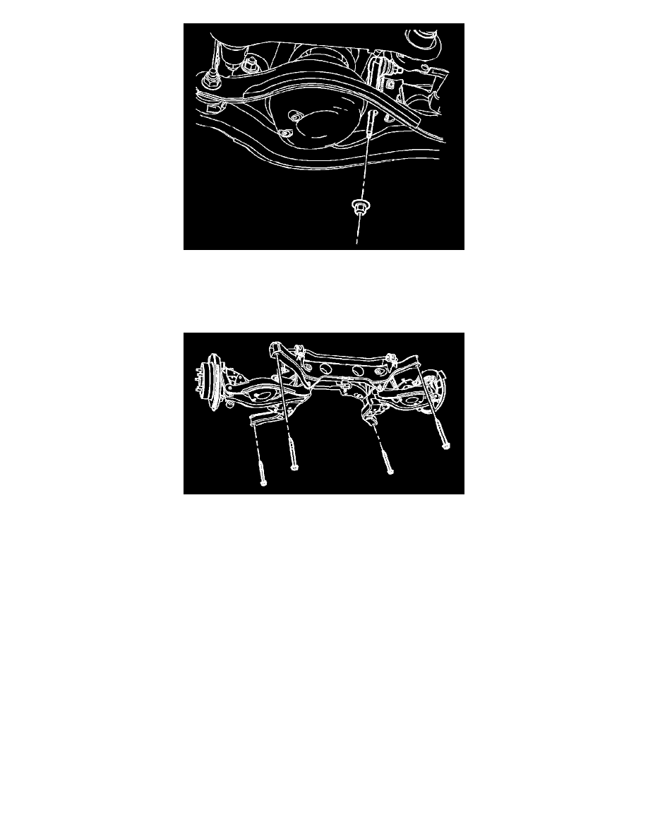
16. Position a transmission jack under the rear support and firmly secure the support to the jack with straps.
17. Remove the 4 rear support to body bolts.
18. Remove he rear support assembly from the vehicle.
19. With the aid of an assistant, remove the rear support from the transmission jack and place it on the floor.
Installation Procedure
CAUTION:
Refer to [Fastener Notice].
1. If a new rear support is being installed, a transfer of components is necessary.
^
Upper Control Arms
Tightening torque
Tighten the upper control arm to rear support nut and bolt to 160 Nm (118 ft. lbs.).
^
Lower Control Arms
Tightening torque
Tighten the lower control arm to rear support nut and bolt to 110 Nm (81 ft. lbs.).
^
Stabilizer bar and insulators
Tightening torque
^
Tighten the stabilizer shaft insulator clamp bolts to 70 Nm (52 ft. lbs.).
^
Tighten the stabilizer link to stabilizer shaft nut to 57 Nm (42 ft. lbs.).
^
Knuckles - The lower control arm to knuckle bolt/nut will be installed and tightened when the coil spring is installed later in this procedure.
Tightening torque
Tighten upper control arm to knuckle bolt and nut to 160 Nm (118 ft. lbs.).
2. With the aid of an assistant, position the rear support onto the transmission jack and firmly secure the support to the jack with straps.
3. Position the rear support assembly to the vehicle.