
XL-7 2WD V6-3.6L (2007)
runout encountered as a result of mounting the tire and wheel assembly on the vehicle, as opposed to the balance which was achieved on the
off-vehicle balancer.
In order to perform an on-vehicle balancing procedure, carefully follow the on-vehicle balancer manufacturer's specific operating instructions and
carefully consider the following information before proceeding:
^
Vehicles equipped with low profile, wide tread path, high performance tires and wheels are susceptible to small amounts of dynamic imbalance.
^
When performing an on-vehicle balance, great care must be taken when placing the wheel balance weights on the wheels. If the wheel balance
weights are not placed accurately, they can actually induce dynamic imbalance and thus increase the severity of the vibration.
^
Inspect the vehicle wheel bearings to ensure that they are in good condition.
^
Thoroughly inspect all on-vehicle balancing equipment and ensure that it is fully within the manufacturer's recommended specifications.
^
Do not remove the off-vehicle balance weights. The purpose of on-vehicle balance is to fine tune the assembly balance already achieved
off-vehicle, not to start over.
^
Leave all wheel trim installed whenever possible.
^
If the on-vehicle balancer calls for more than 56 g (2 oz) of additional weight, split the weight between the inboard and outboard flanges of the
wheel, so as not to upset the dynamic balance of the assembly achieved in the off-vehicle balance.
^
If available, tape-off an area on top of the fenders and the quarter panels, then place the vibration sensor of the J 38792-A on the fender or quarter
panel above the specific tire and wheel assembly while it is being on-vehicle balanced.
The J 38792-A will provide a visual indication of the amplitude of the vibration, and the effect that the on-vehicle balance has on it.
Tire-to-Wheel Match-Mounting (Vectoring)
Tire-to-Wheel Match-Mounting (Vectoring)
NOTE:
After remounting a tire to a wheel or after replacing a tire and/or a wheel, remeasure the tire and wheel assembly runout in order to verify that the
amount of runout has been reduced and brought to within tolerances. Ensure that the tire and wheel assembly is properly balanced before reinstalling
to the vehicle.
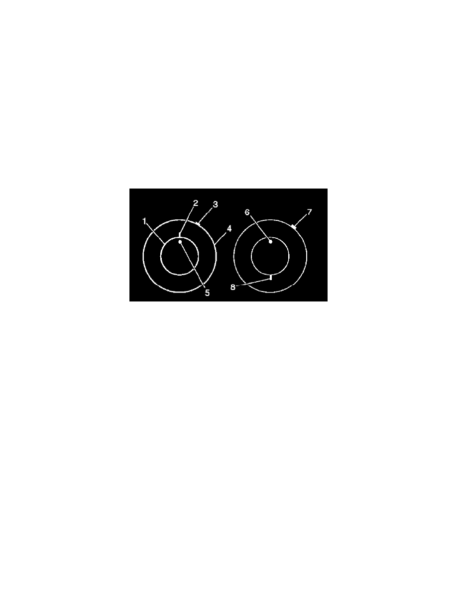
1. Mark the location of the high spot (3) on the tire as determined during the off-vehicle tire and wheel assembly runout measurement.
2. Place a reference mark (2) on the tire sidewall at the location of the valve stem (5).
^
Always refer to the valve stem as the 12 o'clock position.
^
Refer to the location of the high spot (3) by its clock position on the wheel, relative to the valve stem.
3. Mount the tire and wheel assembly on a tire machine and break down the bead. Do not dismount the tire from the wheel at this time.
4. Rotate the tire 180 degrees on the rim so that the valve stem reference mark (8) is now at the 6 o'clock position in relation to the valve stem (6).
You may need to lubricate the bead in order to easily rotate the tire on the wheel.
5. Reinflate the tire and seat the bead properly.
6. Mount the assembly on the tire balancer and remeasure the runout. Mark the new location of the assembly runout high spot on the tire.
7. If the assembly runout has been reduced and is within tolerance, no further steps are necessary. Balance the tire and wheel assembly, then install
the assembly to the vehicle.
8. If the clock location of the high spot remained at or near the original clock location of the high spot (7) and the assembly runout has NOT been
reduced, the wheel is the major contributor to the assembly runout concern.