
4 Runner 2WD L4-2693cc 2.7L DOHC MFI (1997)
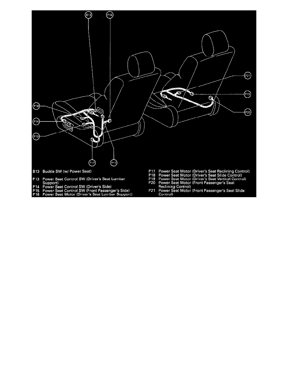
Position Of Parts In Seat (Fig 34)
Service Hints
B13 BUCKLE SW
1-2:
Open with Drivers seat belt in use
D16 DOOR COURTESY SW
1-GROUND:Closed with Front LH Door open
U 1-A, B UNLOCK WARNING SW
2-1:
Closed with Ignition key in Cylinder
I15-A INTEGRATION RELAY
7-GROUND:Always continuity
A-5-GROUND:Continuity with Front LH Door open
A-7-GROUND:Approx. 12 Volts with Ignition key in Cylinder
A-3-GROUND:Continuity unless Drivers seat belt in use
A-2-GROUND:0 Volts for 4-8 Seconds with Ignition SW ON and 12 Volts 4-8 Seconds after Ignition SW ON
6-GROUND:Approx. 12 Volts with Ignition SW ON
12-GROUND:Always Approx. 12 Volts
System Outline
Current always flows to TERMINAL 12 of the integration Relay through the DOME fuse.
1. SEAT BELT WARNING SYSTEM
When the Ignition SW is turned ON, current flows from the GAUGE fuse to TERMINAL 6 of the integration Relay. At the same time, current
flows to TERMINAL A-2 of the Relay from the GAUGE fuse through the seat belt Warning light. This current activates the integration Relay
and, for Approx. 4-8 seconds, current flowing through the warning light flows from TERMINAL A-2 of Relay --> TERMINAL 7 -->
GROUND, causing the warning light to light up. At the same as the warning light lights up, a buckle SW ON signal is input to TERMINAL A-3
of the Relay, the current flowing to TERMINAL 1 of the Buckle SW --> TERMINAL 7 --> GROUND and the seat belt warning buzzer sounds