
Celica Supra L6-2759cc 5M Ser (1982)
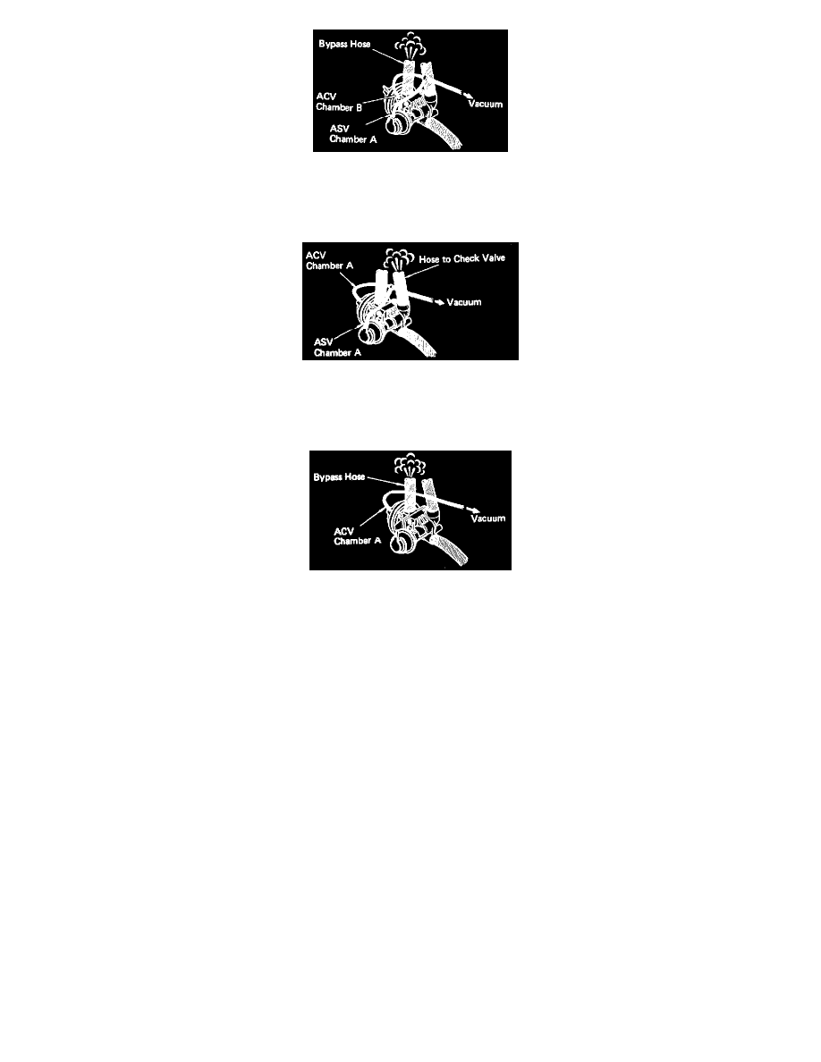
Fig.83 - Testing Air Control Valve
3. With engine idling, apply vacuum directly to air control valve chamber "B" and air switching valve chamber "A", Fig. 83. Compressed air should
be discharged from air by-pass hose at idle.
Fig.84 - Testing Air Control Valve
4. Release vacuum from air control valve chamber "B" and apply vacuum directly to air control valve chamber "A" and air switching valve chamber
"A", Fig. 84. Compressed air should be discharged from air hose to check valve at idle.
Fig.85 - Testing Air Control Valve
5. Release vacuum from air switching valve chamber "A" and apply vacuum directly to air control valve chamber "A", Fig. 85. Compressed air
should be discharged from by-pass hose at idle.
6. Connect suitable tester to check valve air hose.
7. Apply vacuum directly to air control valve chamber "A" and air switching valve chamber "A".
8. Close off orifice of tester.
9. Gradually increase engine speed and measure relief valve opening pressure. Opening pressure should be 4.7 to 6.8 psi.
10. Remove tester and reconnect air and vacuum hoses to proper locations.