
Celica Supra L6-2759cc 5M Ser (1982)
Air Flow Meter/Sensor: Testing and Inspection
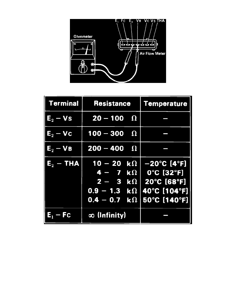
Fig. 4 Air flow meter connector terminals
Fig. 24 Resistance specifications
1. Disconnect air flow meter electrical connector and measure resistance between connector terminals, Fig. 4.
2. Readings obtained should correspond to resistance values shown in chart, Fig. 5.
3. With air flow meter removed from vehicle, check resistance at electrical connector, Fig. 4. With measuring plate fully closed, resistance between
terminals E(2) and VS should be 20-100 ohms. In any other position reading should be 20-1000 ohms.