
Corolla LE Sedan L4-1762cc 1.8L DOHC MFI (1998)
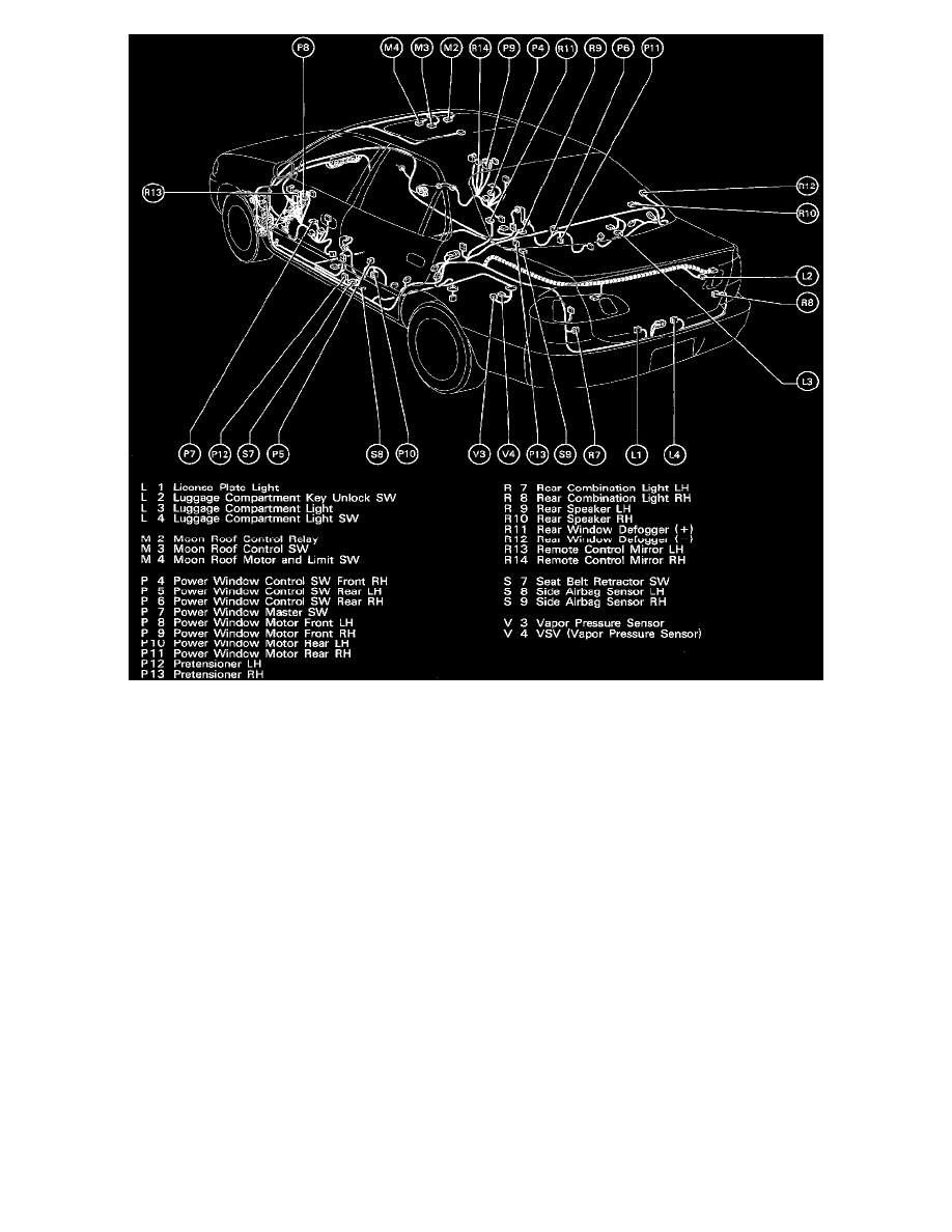
Position Of Parts In Body (Part 2 Of 2) (Fig 39)
Service Hints
U 1 UNLOCK WARNING SW
1-2:
Closed with the ignition key in cylinder
S 7 SEAT BELT RETRACTOR SW
1-2:
Open with the driver's seat belt in use
I11 (A) INTEGRATION RELAY
9-GROUND:
Approx. 12 Volts with the ignition SW at ON position
7-GROUND:
Always continuity
A-5-GROUND:
Continuity with the driver's seat belt not use
A-4-GROUND:
Continuity with the ignition key in cylinder
A-3-GROUND:
Always approx. 12 Volts
8-GROUND:
Continuity with the front LH door open
System Outline
The current is applied at all times to TERMINAL (A) 3 of the integration relay through the DOME fuse.
1. SEAT BELT WARNING SYSTEM
When the ignition SW is turned ON and the driver's seat belt is not used, the current flows from the GAUGE fuse to the integration relay at the
same time, the current flows to TERMINAL 9 of the relay from the GAUGE fuse through TERMINAL (A) 9 of the integration relay to
TERMINAL (D) 2 of the seat belt warning light. This current activates the integration relay and, at intervals of approx. 0.6 seconds, current
flowing through the warning light flows from TERMINAL (A) 2 of the relay to TERMINAL 7 to GROUND, causing the warning light to blink.
At the same time as the warning light blinks, a seat belt retractor SW OFF signal is input to TERMINAL (A) 5 of the relay, the current flowing to
TERMINAL (A) 3 of the relay flows from TERMINAL 7 to GROUND and the seat belt warning buzzer goes ON for approx. 6 seconds.