
Previa Van DX 4WD L4-2438cc 2.4L DOHC SC MFI (1997)
4-GROUND: 0 Volts for 4-8 Seconds with the ignition SW ON and approx.
12 Volts for 4-8 Seconds after the ignition SW is turned ON
9-GROUND: Approx. 12 Volts with the ignition SW ON
I 8 WARNING SW (IGNITION KEY) [IGNITION SW]
1-5:
Closed with the ignition key in the cylinder
System Outline
Current always flows to TERMINAL 8 of the seat belt warning relay through the DOME fuse.
1. SEAT BELT WARNING SYSTEM
When the ignition SW is turned ON, current flows from the GAUGE fuse to TERMINAL 9 of the seat belt warning relay. At the same time,
current flows to TERMINAL 4 of the relay from the GAUGE fuse through the seat belt warning light. This current activates the seat belt warning
relay and, for approx. 4-8 Seconds, current flowing through the warning light flows from TERMINAL 4 of the relay --> TERMINAL 1 -->
GROUND, causing the warning light to light up. At the same time a buckle SW OFF signal is input to TERMINAL 10of the relay, the current
flowing to TERMINAL 8 of the relay flows to TERMINAL 1 --> GROUND and the seat belt warning buzzer sounds for approx. 4-8 Seconds.
However, if the seat belt is put on during this period (while the buzzer is sounding), the signal input to TERMINAL 10 of relay stops and the
current flow from TERMINAL 8 of the relay --> TERMINAL 1 --> GROUND is cut, causing the buzzer to stop.
2. KEY REMINDER SYSTEM
With the ignition key inserted in the key cylinder (warning SW (ignition key) ON). The ignition SW still of and door open (door courtesy SW ON
), when a signal is input to TERMINAL 11 of the relay, the seat belt warning relay operates, current flows from TERMINAL 9 of the relay -->
TERMINAL 1 --> GROUND, and the Key Reminder buzzer sounds.
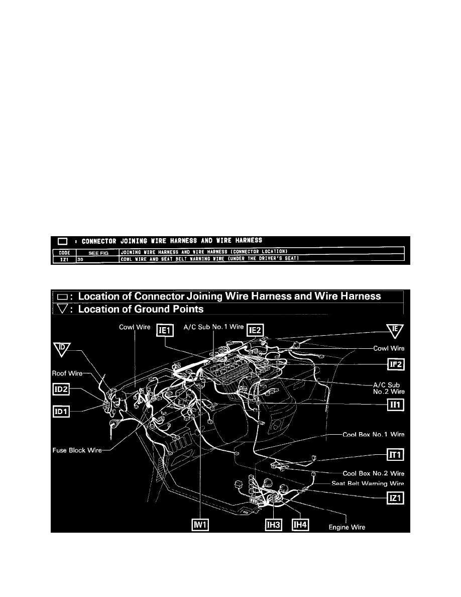
Connector Joining Wire Harness and Wire Harness
Connector Joining Wire Harness and Wire Harness
Location Of Connector Joining Wire Harness And Wire Harness Ground Points (Fig 30)
Ground Points